CHILLED WATER SENSOR
On units WHR-040D thru
240D.
the chilled water sensor is
factory installed in the leaving water connection on the
evaporator. For detailed specifications regarding the chilled
water sensor or any other sensors/transducers, refer to IM 493.
Care should be taken not to damage the sensor cable or lead-
wires when working around the unit. It is also advisable to
check the leadwire before running the unit to be sure that it
is firmly anchored and not rubbing on the frame or any other
Table
5.
component. Should the sensor ever be removed from the well
for servicing, care should be taken as not to wipe off the heat
conducting compound supplied in the well.
Figure 6.
Thermostat Well Installation
TEMPERATURE SENSOR
LOCATICJN
NOTE: See IM 493 for additional thermostat information.
CAUTION: The thermostat bulb should not be exposed to
water temperatures above 125°F since this will damage the
control.
FLOW
SWITCH
A WATER FLOW SWITCH MUST SE MOUNTED in either the
entering or leaving water line to insure that there will be ade-
quate water flow and cooling load to the evaporator before
the unit can start. This will safeguard against slugging the
compressors on startup. It also serves to shut down the unit
in the event that water flow is interrupted to guard against
evaporator freeze-up.
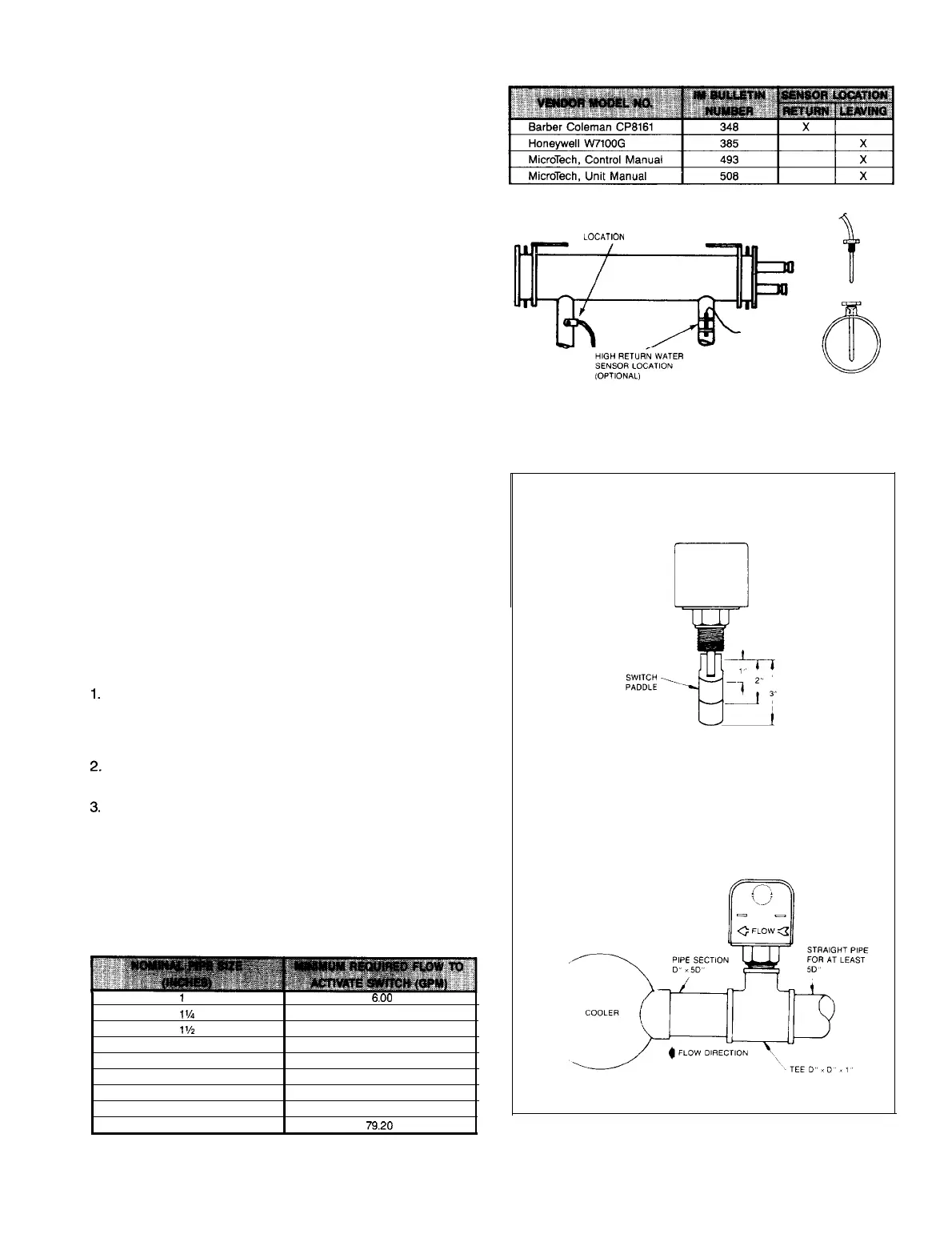
Fioure 7.
A flow switch is available from under ordering number
1750338-00. It is a “paddle” type switch and adaptable to any
pipe size from
1”
to
6”
nominal. Certain minimum flow rates
are required to close the switch and are listed in Table 6. In-
stallation should be as shown in Figure 7. The flow switch
should be wired per actual unit wiring diagram found on the
inside of the unit control panel door or refer to IM 493.
Apply pipe sealing compound to only the threads of the
switch and screw unit into
D”x
D”x
1”
reducing tee (see
Figure
7).
The flow arrow must be pointed in the correct
direction.
Piping should provide a straight length before and after
the flow switch of at least five times the pipe diameter.
Trim flow switch paddle if needed to fit the pipe diameter.
Make sure paddle does not hang up in pipe.
CAUTION: Make sure the arrow on the side of the switch is
pointed in the proper direction of flow. The flow switch is
designed to handle the control voltage and should be con-
nected according to the wiring diagram (see wiring diagram
inside control box door).
Table 6. Flow Switch Minimum Flow Rates
1
6.00
1%
9.80
l'h 12.70
2 18.80
2%
24.30
3
30.00
4
39.70
5
58.70
FLOW SWITCH
VIEW FROM END OF COOLER
IM 508 I Page 7
 Loading...
