After re-assembling the evaporator, a small amount of
refrigerant should be introduced by momentarily opening the
manual liquid line valve. A leak check should then be
per-
formed on the evaporator.
Tube removal can only take place after the leaking tube is
located. One method that would work would be to subject each
tube to
air pressure by plugging each end and, with a pressure
gauge attached to one of the end plugs, observing if there
is a loss of air pressure over a period of a minute or two.
Another method is to place a cork plug in each tube on both
ends of the cooler and applying pressure to the shell of the
cooler. After a period of time, the pressure will leak from the
shell into the leaking tube or tubes and pop out the cork plug.
Figure
31. Top View of Typical Dual Circuit Shell-and-Tube Evaporator
Water Baffles
Liquid Connections
Suction Connections
L
Refrigerant Tubes
Shell
Water Nozzles
WATER COOLED CONDENSER
The condenser is of the shell-and-tube type with water
flow-
ment W units. Heat recovery units have integral subcoolers
ing through the tubes and refrigerant in the shell. External in the tower condensers. All condensers are equipped with
finned copper tubes are rolled into steel tube sheets. Integral 450 psig relief valves. Heat recovery condensers are free-
subcoolers are incorporated on 40 ton and larger Arrange- draining to the lower (tower) condensers and do not subcool.
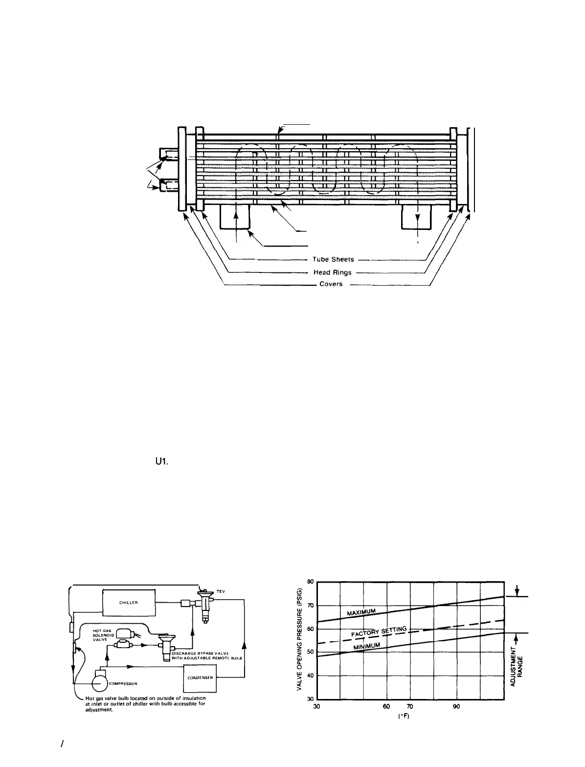
HOT GAS BYPASS (OPTIONAL)
This option allows passage of discharge gas to the evaporator
permitting operation at lower loads than available with com-
pressor unloading. It also keeps the velocity of refrigerant gas
high enough for proper oil return at light load conditions. A
solenoid valve in the hot gas bypass line is wired in parallel
with the compressor unloader
Ul.
Thus, the hot gas solenoid
cannot open unless the compressor is operating in an un-
loaded mode. If only one hot gas valve is specified for the
unit, the hot gas bypass is wired in the first refrigerant circuit
and the lead-lag switches are therefore eliminated. The hot
gas bypass option is also available for the second refrigerant
circuit whereby the lead-lag switches remain.
The pressure regulating valve is factory set to begin open-
ing at 58 psig (32°F for R-22). This setting can be changed
Figure 32.
Hot Gas Bypass Piping Diagram
f
I
I
b,
TL”
by changing the pressure of the air charge in the adjustable
bulb. To raise the pressure setting, remove the cap on the
bulb and turn the adjustment screw clockwise. To lower the
setting, turn the screw counterclockwise. Do not force the ad-
justment beyond the range it is designed for, as this will
damage the adjustment assembly.
The regulating valve opening point can be determined by
slowly reducing the system load while observing the suction
pressure. When the bypass valve starts to open, the refrigerant
line on the evaporator side of the valve will begin to feel warm
to the touch.
CAUTION: The hot gas line may become hot enough to
cause injury in a very short time; care should be taken dur-
ing valve checkout.
Figure 33. Hot Gas Bypass Adjustment Range
30
40
50
60
70
80
90
100
110
TEMPERATURE
(“F)
AT BULB LOCATION
Page 46
I
IM 508
 Loading...