DUAL CONDENSER HEAT RECOVERY - ARRANGEMENT H
Dual condenser heat recovery chiller models have two water
cooled condensers per refrigerant circuit. The upper con-
denser is the heat recovery condenser and is piped into the
building’s hot water system. The lower condenser is the tower
condenser and is piped to an open cooling tower. Condens-
ing is done in either the tower condenser or heat recovery
condenser, or partial condensing is done in each. The tower
and heat recovery water circuits are independent and do not
intermix. This use of an open tower and the closed heat
recovery loop prevents fouling of the building’s heating
system.
A subcooling circuit is provided in the tower condenser to
provide optimum cooling efficiency. When the unit is
operating on maximum heat recovery, the cooling tower will
be modulated down to its minimum capacity, usually about
5% of full capacity. This provides subcooling for the system
during heat recovery operation. Water can be heated up to
135°F in the heat recovery condensers to satisfy a heating
load. If all of the condenser heat of rejection cannot be
used, the remainder is rejected out through the cooling tower.
The cooling tower should be sized to reject all of the con-
denser heat during summer operation. Freeze protection for
the cooling tower must be provided if it is to operate in below
freezing temperatures, Adequate capacity control must be
provided to maintain a constant water temperature leaving
the cooling tower. Head pressure and water temperature are
controlled by the tower capacity control. Fan cycling and
modulating fan discharge dampers should be used. Consult
Figure
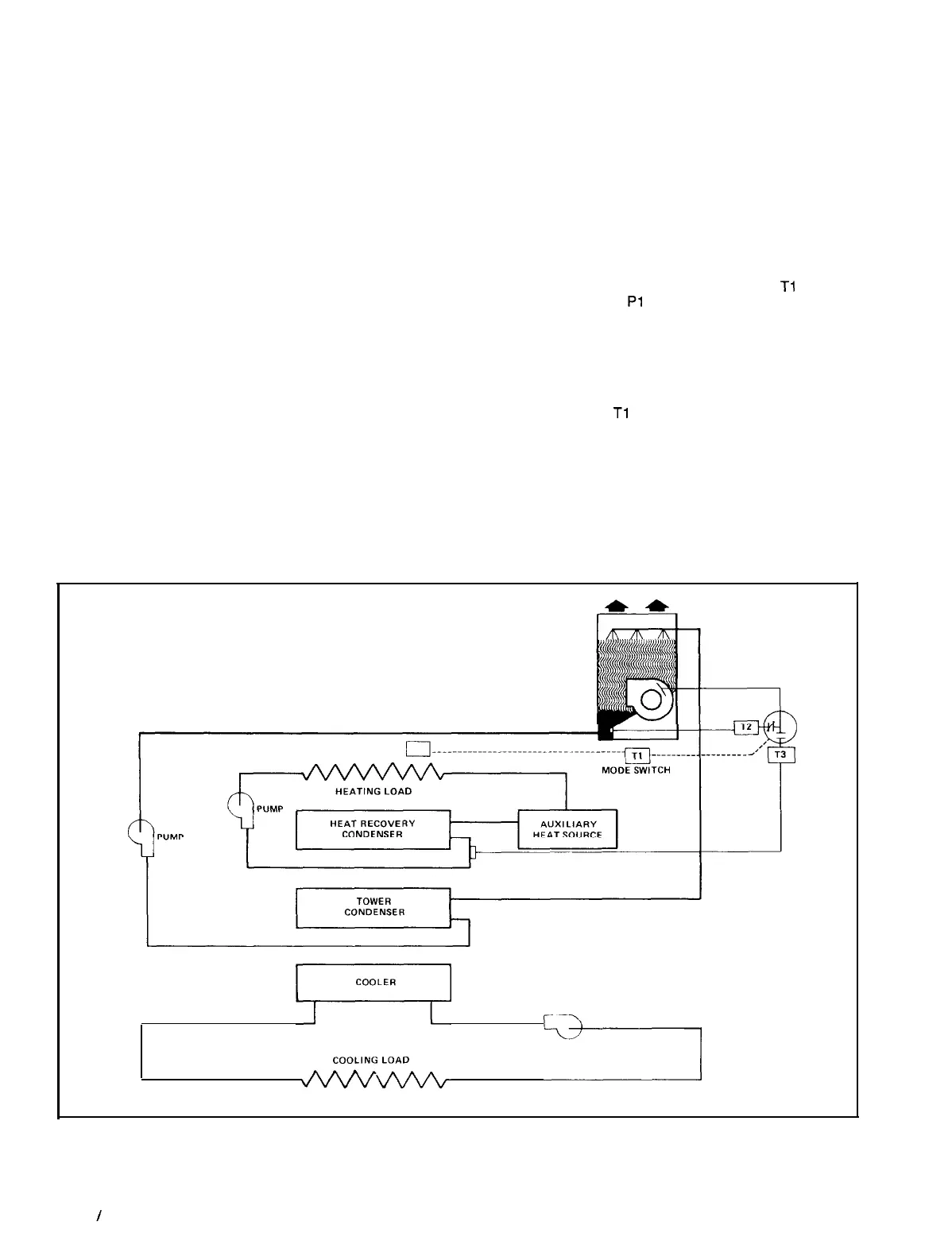
12. Typical Dual Condenser (Per Circuit) Heat Recovery
the cooling tower manufacturer for information on specific
applications.
If the available condenser heat cannot satisfy all of the heat
load, an auxiliary heat source must be provided. The aux-
iliary heat source should be located between the heat
recovery condenser and the heat load and interlocked with
the cooling tower so that auxiliary heat is not being supplied
unless the cooling tower is modulated down all the way. The
chiller operation is always controlled by the building’s cool-
ing load and not the heating load.
TYPICAL OPERATION
-
On a call for cooling the chiller
starts. If a heating load is sensed by mode switch
Tl
, the heat
recovery water pump
Pl
will start and the cooling tower
dampers will modulate to control the heat recovery condenser
by means of proportional temperature controller T3. If max-
imum heat recovery is required, the tower dampers close and
the fans shut off. The tower will then provide
only
subcool-
ing. If more heat is required than the heat recovery con-
densers can provide, the auxiliary heat source is activated.
When mode switch
Tl
senses that a heating load no longer
exists, the heat recovery pump shuts off and the cooling tower
modulates to control the entering tower condenser water
temperature by means of proportional controller T2 and a sen-
sor located in the tower sump. Proportional controller T2 is
set at a temperature lower than T3 to provide optimum
efficiency.
COOLING TOWER
COOLER
PUMP
‘&k’
------j
NOTE: The schematic shows one refrigerant circuit. Heat recovery WHR models with two refrigerant circuits
have two heat recovery condensers and two tower condensers.
Page 12
/
IM 508
 Loading...
