Mercury Security © 2018 LP1501 DOC 10107-0064 REV 1.01 Page 4
6. Communication Wiring:
The LP1501 controller communicates to the host via the on-board 10-BaseT/100Base-TX Ethernet
interface.
7. Reader/Serial I/O Device Wiring:
Reader port 1 supports TTL (D1/D0, Clock/Data), F/2F, or 2-wire RS-485 device(s). Reader port 2 supports
TTL (D1/D0, Clock/Data), or F/2F. Power to reader port 1 is 12 Vdc at 300 mA maximum. The reader
connected to reader port 2 may be powered from the 12 Vdc auxiliary power supply output; TB4-1 and TB4-
2. Readers that require different voltage or have high current requirements should be powered separately.
Refer to the reader manufacture specifications for cabling requirements. In the 2-wire LED mode, the
buzzer output is used to drive the second LED. Reader port configuration is set via the host software.
Reader port 1 can support up to eight 2-wire RS-485 remote serial I/O devices using MSP1 protocol or up
to two OSDP devices. If two OSDP devices are used, reader port 2 will not support a third reader. If only
one OSDP device is configured, then reader port 2 is available for a second reader. The maximum cable
length is 2000 ft. (610 m). Do not terminate any RS-485 devices connected to reader port 1.
When powering remote device(s) from the LP1501, be cautious not to exceed the maximum current limit.
Cable gauge must also be evaluated. See specifications section for details.
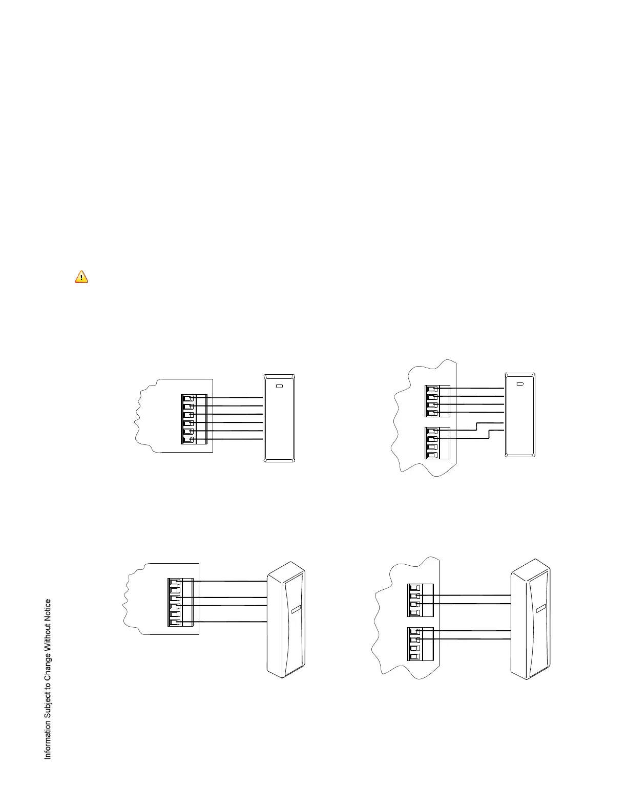
Reader Wiring Diagrams:
 Loading...