11
90-10225R30
GB
gob27
1
2
3
4
5
6
7
8
9
10
ob
GENERAL INFORMATION
obn5
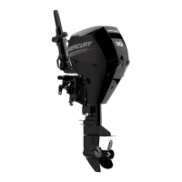
COMPONENT IDENTIFICATION
1. Top Cowl
2. Bottom Cowl
3. Water Pump Indicator Hole
4. Drive Shaft Housing
5. Anti-Ventilation Plate
6. Trim Tab
7. Auxiliary Tilt Switch
8. Transom Brackets
9. Gear Case
10.Cooling Water Intake Holes
goc15
1-2
3
a
oc
INSTALLATION
oca6
INSTALLING OUTBOARD
WARNING
Before operation, the outboard must be correctly installed with four
mounting bolts shown. Failure to correctly fasten outboard could result
in outboard ejecting off boat transom causing serious injury, death, or
property damage.
1 We strongly recommend that your dealer install your outboard and related
accessories to ensure proper installation and good performance. If you install
the outboard yourself, follow instructions in the Outboard Installation Manual
which is provided with the outboard.
2 The outboard must be secured to the transom with the four 1/2 inch diameter
mounting bolts and locknuts provided with the outboard. Install two bolts thru
the upper set of holes and two bolts thru the lower set of holes.
oci1
Maximum Outboard Mounting Height
3 The mounting height (a) of the outboard must not exceed 25 in. (635 mm) for
EL models and 30 in. (762 mm) for EXL models. Mounting the outboard higher
may cause damage to the gear case components.
goc11
ocb1
PROPELLER SELECTION
For best all around performance from your outboard/boat combination, select a
propeller that allows the engine to operate in the upper half of the recommended
full throttle RPM range with the boat normally loaded (refer to Specifications). This
RPM range allows for better acceleration while maintaining maximum boat speed.
If changing conditions cause the RPM to drop below the recommended range
(such as warmer, more humid weather, operation at higher elevations, increased
boat load, or a dirty boat bottom/gear case) a propeller change or cleaning may
be required to maintain performance and ensure the outboards durability.
Check full-throttle RPM using an accurate tachometer with the engine trimmed out
to a balanced-steering condition (steering effort equal in both directions) without
causing the propeller to “break loose.”
god9
od
TRANSPORTING
odc1
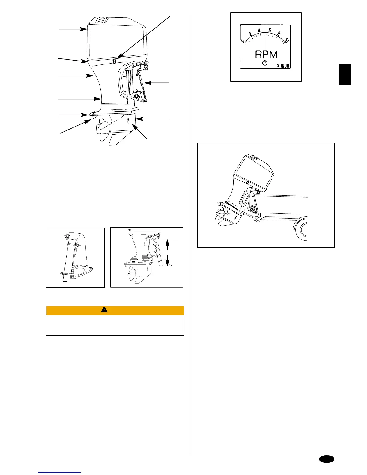
TRAILERING BOAT/OUTBOARD
Trailer your boat with the outboard tilted down (vertical operating position).
If additional ground clearance is required, the outboard should be tilted up using
an accessory outboard support device. Refer to your local dealer for
recommendations. Additional clearance may be required for railroad crossings,
driveways and trailer bouncing.
IMPORTANT: Do not rely on the power trim/tilt system or tilt support lever
to maintain proper ground clearance for trailering. The outboard tilt support
lever is not intended to support the outboard for trailering.
Shift the outboard to forward gear. This prevents the propeller from spinning freely.
 Loading...