20
90-10126R40
GB
goh111
a
c
b
d
oh
MAINTENANCE
ohi5
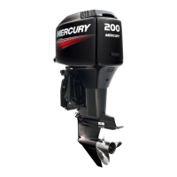
STEERING LINK ROD FASTENERS
IMPORTANT: The steering link rod that connects the steering cable to the
engine must be fastened using special washer head bolt (“a” – Part Number
10-849838) and self locking nylon insert locknuts (“b” & “c” – Part Number
11-34863). These locknuts must never be replaced with common nuts (non
locking) as they will work loose and vibrate off freeing the link rod to
disengage.
WARNING
Disengagement of a steering link rod can result in the boat taking a full,
sudden, sharp turn. This potentially violent action can cause occupants
to be thrown overboard exposing them to serious injury or death.
Assemble steering link rod to steering cable with two flat washers (d) and self
locking nylon insert locknut (“b” – Part Number 11-34863). Tighten locknut (b) until
it seats, then back nut off 1/4 turn.
Assemble steering link rod to engine with special washer head bolt (“a” – Part
Number 10-849838) and self locking nylon insert locknut (“c” – Part Number
11-34863). First torque bolt (a) to 20 lb. ft. (27.1 N·m), then torque locknut (c) to
20 lb. ft. (27.1 N·m).
goh72
1
a
b
c
ohj13
FUSES
MODELS WITH CARBURETORS
IMPORTANT: Always carry spare SFE 20 AMP fuses.
The electrical wiring circuits on the outboard are protected from overload by fuses.
If a fuse is blown, try to locate and correct the cause of the overload. If the cause
is not found, the fuse may blow again.
1 Open the fuse holder and look at the silver colored band inside the fuse. If band
is broken, replace the fuse. Replace fuse with a new fuse with the same rating.
The fuses and circuits are identified as follows:
a. Accessories and Starting Circuit – 20 AMP Fuse.
b. Upper Voltage Regulator – 20 AMP Fuse.
c. Lower Voltage Regulator – 20 AMP Fuse.
1
a
c
b
d
15
ohj14
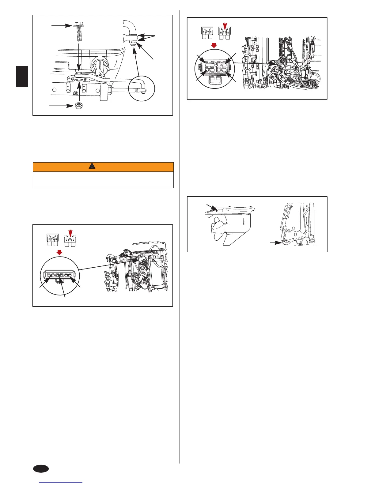
FUSES
MODELS WITH ELECTRONIC FUEL INJECTION (EFI)
IMPORTANT: Always carry spare 15 and 20 AMP fuses.
The electrical wiring circuits on the outboard are protected from overload by fuses
in the wiring. If a fuse is blown, try to locate and correct the cause of the overload.
If the cause is not found, the fuse may blow again.
1 Open the fuse holder and look at the silver colored band inside the fuse. If band
is broken, replace the fuse. Replace fuse with a new fuse with the same rating.
The fuses and circuits are identified as follows:
a. SmartCraft Data Bus Circuit – 15 AMP Fuse.
b. Accessories – 20 AMP Fuse.
c. Ignition Coil Circuit – 20 AMP Fuse.
d. Electric Fuel Pump/ECM Driver Power/Oil Pump Circuit – SFE 20 AMP
Fuse.
1
b
a
ohk16
CORROSION CONTROL ANODE
1 The gear case has two corrosion control anodes (a). Another anode (b) is
installed on the bottom of the transom bracket assembly. An anode helps
protect the outboard against galvanic corrosion by sacrificing its metal to be
slowly eroded instead of the outboard metals.
Each anode requires periodic inspection especially in salt water which will
accelerate the erosion. To maintain this corrosion protection, always replace the
anode before it is completely eroded. Never paint or apply a protective coating on
the anode as this will reduce effectiveness of the anode.
ohn1
BATTERY INSPECTION
The battery should be inspected at periodic intervals to ensure proper engine
starting capability.
IMPORTANT: Read the safety and maintenance instructions which
accompany your battery.
1. Turn off the engine before servicing the battery.
2. Add water as necessary to keep the battery full.
3. Make sure the battery is secure against movement.
4. Battery cable terminals should be clean, tight, and correctly installed. Positive
to positive and negative to negative.
5. Make sure the battery is equipped with a nonconductive shield to prevent
accidental shorting of battery terminals.
 Loading...