19
90-10185R30
GB
gof60
21
of
MAINTENANCE
ohf2
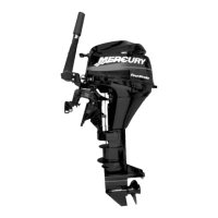
TOP COWL REMOVAL AND INSTALLATION
Removal
1 Unlock the rear latch by pushing lever down.
2 Lift rear of cowl and disengage front hook.
Installation
Engage the front hook and push cowl back over the cowl seal.
Push cowl down and move the rear latch lever up to lock.
ohn1
BATTERY INSPECTION
The battery should be inspected at periodic intervals to ensure proper engine
starting capability.
IMPORTANT: Read the safety and maintenance instructions which
accompany your battery.
1. Turn off the engine before servicing the battery.
2. Add water as necessary to keep the battery full.
3. Make sure the battery is secure against movement.
4. Battery cable terminals should be clean, tight, and correctly installed. Positive
to positive and negative to negative.
5. Make sure the battery is equipped with a nonconductive shield to prevent
accidental shorting of battery terminals.
gof69
1
ohh3
FUEL SYSTEM
WARNING
Avoid serious injury or death from gasoline fire or explosion. Carefully
follow all fuel system service instructions. Always stop the engine. DO
NOT smoke or allow open flames or sparks in the area while servicing any
part of the fuel system.
Before servicing any part of the fuel system, stop engine and disconnect the
battery. Drain the fuel system completely. Use an approved container to collect
and store fuel. Wipe up any spillage immediately. Material used to contain spillage
must be disposed of in an approved receptacle. Any fuel system service must be
performed in a well- ventilated area. Inspect any completed service work for signs
of fuel leakage.
Fuel Line Filter
1 Inspect the fuel line filter. If the filter appears to be contaminated, remove and
replace.
IMPORTANT: Visually inspect for fuel leakage from the filter connections by
squeezing the primer bulb until firm, forcing fuel into the filter.
Fuel Line Inspection
Visually inspect the fuel line and primer bulb for cracks, swelling, leaks, hardness,
or other signs of deterioration or damage. If any of these conditions are found, the
fuel line or primer bulb must be replaced.
gof70
21
a
b
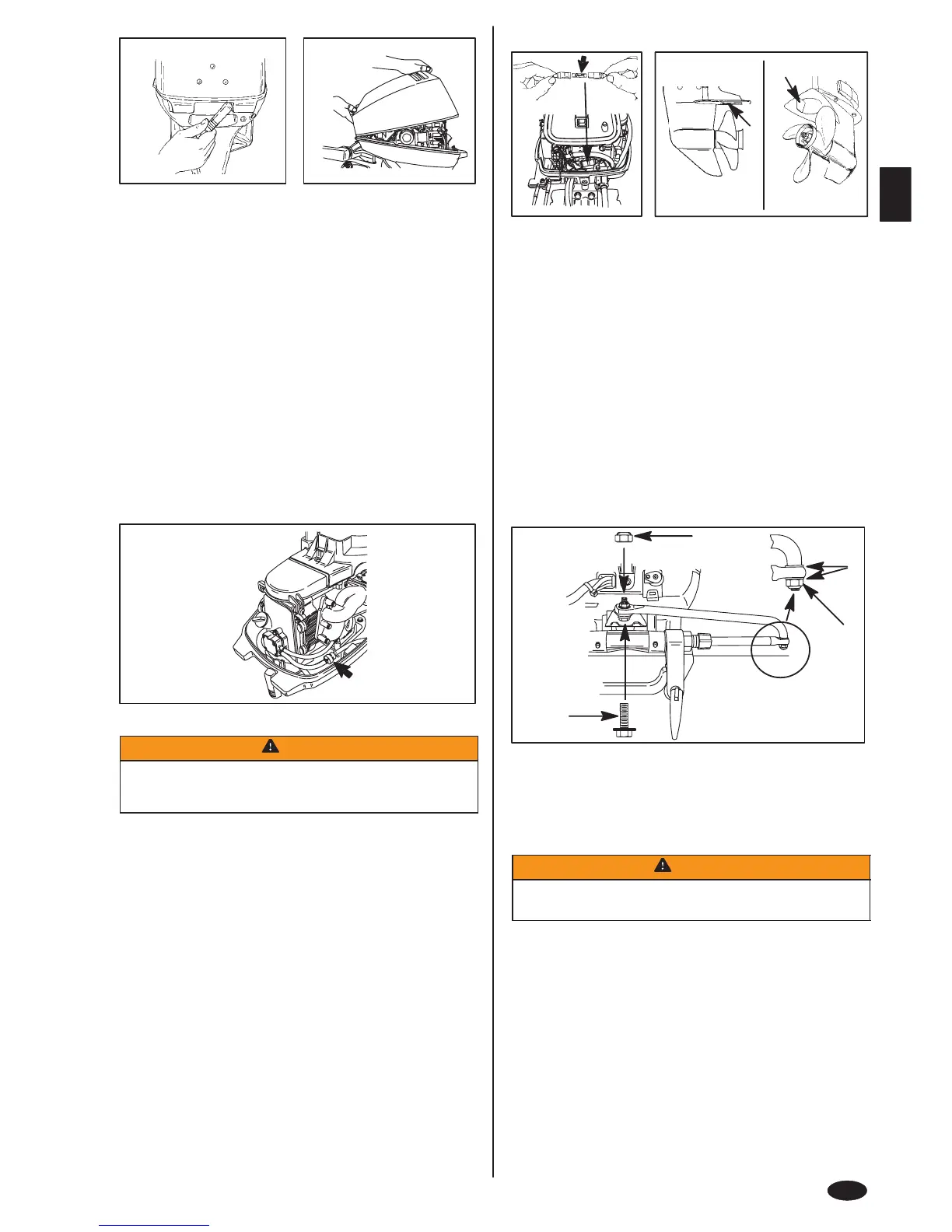
omc3
FUSE REPLACEMENT - ELECTRIC START MODELS
IMPORTANT: Always carry spare 20 AMP fuses.
The electric starting circuit is protected from overload by a 20 AMP fuse. If the fuse
is blown, the electric starter motor will not operate. Try to locate and correct the
cause of the overload. If the cause is not found, the fuse may blow again.
1 Open the fuse holder and look at the silver colored band inside the fuse. If band
is broken(a), replace the fuse. Replace fuse with a new fuse with the same
rating.
oth2
CORROSION CONTROL ANODE
Your outboard has a corrosion control anode installed to the gear case. An anode
helps protect the outboard against galvanic corrosion by sacrificing its metal to be
slowly eroded instead of the outboard metals.
2 The anode (a) on standard models and (b) on Bigfoot models requires periodic
inspection especially in salt water which will accelerate the erosion. To
maintain this corrosion protection, always replace the anode before it is
completely eroded. Never paint or apply a protective coating on the anode as
this will reduce effectiveness of the anode.
gof70
a
c
b
d
ohi2
STEERING LINK ROD FASTENERS
IMPORTANT: The steering link rod that connects the steering cable to the
engine must be fastened using special washer head bolt (“a” - Part Number
10-14000) and self locking nuts (“b” & “c” - Part Number 11-34863). These
locknuts must never be replaced with common nuts (non locking) as they
will work loose and vibrate off freeing the link rod to disengage.
WARNING
Disengagement of a steering link rod can result in the boat taking a full,
sudden, sharp turn. This potentially violent action can cause occupants
to be thrown overboard exposing them to serious injury or death.
Assemble steering link rod to steering cable with two flat washers (d) and nylon
insert locknut (“b” - Part Number 11-34863). Tighten locknut (b) until it seats, then
back nut off 1/4 turn.
Assemble steering link rod to engine with special washer head bolt (“a” - Part
Number 10-90041) and locknut (“c” - Part Number 11-34863. First torque bolt (a)
to 20 lb. ft. (27 N·m), then torque locknut (c) to 20 lb. ft. (27 N·m).
 Loading...