INSTALLATION MANUAL
Page 34 of 77 90-864198020
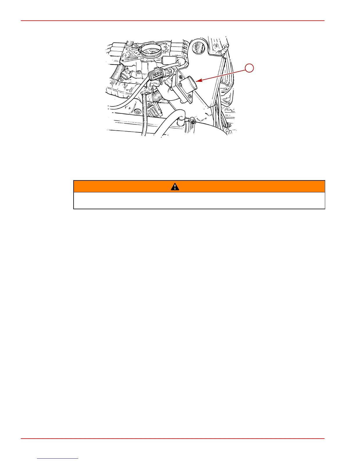
4. Connect the instrumentation wiring harness to engine harness plug at location shown.
78030
a
a-Engine Harness Plug
5. Tighten hose clamp to secure wiring harness to engine harness plug.
Audio Warning System Connections
WARNING
Alarm is not external ignition-proof, therefore, DO NOT mount alarm in engine or
fuel tank compartments.
1. Select a location for audio warning alarm which meets all of the following:
• alarm can be easily heard, yet is out of sight
• alarm can be easily accessed for installation and maintenance
• alarm will remain dry
• alarm is within length limits of the 18 in. purple alarm wire that connects to the “I” terminal
or 12 volt source on switched side of ignition switch.
NOTE: The terminal to which wire is attached must have no voltage when ignition switch
is in the OFF position.
2. Place alarm in desired location and secure to wire bundle with tie-strap provided.
3. Connect PURPLE wire from alarm to any PURPLE wire terminal on instrument gauge
or ignition switch. Tighten connection securely.
4. Connect TAN/BLUE wire from alarm to TAN/ BLUE wire from instrument harness.
5. Place the small (transparent) decals on the bottom of the water temperature and the oil
pressure gauges.
 Loading...