ENGLISH en
17
If performance diminishes, recharge the battery
pack.
The ideal storage temperature is between 10°C and
30°C.
"Li-Power" li-ion battery packs have a capacity and
signal indicator: (15)
- Press the button (14), the LEDs indicate the
charge level.
- If one LED is flashing, the battery pack is almost
flat and must be recharged.
Removing and inserting the battery pack
To remove:
Press the battery pack release button
(13) and pull the battery pack (16) downwards
.
To fit:
Slide in the battery pack (16) until it engages.
6.3 Attaching the additional handle
Always work with the additional handle
attached (7)! Attach the additional handle on
the left or right of the machine and secure.
6.4 Install safety guard
For safety reasons, always use the safety
guard provided for the respective wheel! See
also chapter 11.
Safety guard for grinding
Designed for work with roughing wheels, flap
sanding pads, diamond cut-off wheels.
See page 2, illustration E.
- Place the safety guard (6) in the position indi-
cated.
- Push the lever and turn the safety guard until the
closed section is facing the operator.
- Release the lever and turn the safety guard
until the lever engages.
- Make sure that the guard is seated securely: the
lever must engage and you should not be able to
turn the safety guard.
Use only accessories that
are covered by at least 3.4
mm by the safety guard.
Before carrying out any modifications, remove
the battery pack from the machine and pull the
mains plug from the socket. The machine must be
switched off and the spindle must be at a standstill.
For reasons of safety, attach the parting guard
before performing parting work (see chapter
11. Accessories).
7.1 Locking the spindle
Press in the spindle locking button (5) only
when the spindle is stationary!
- Press in the spindle locking button (5) and turn the
spindle (4) by hand until you feel the spindle
locking button engage.
7.2 Placing the grinding wheel in position
See illustration C on page 2.
- Fit the support flange (3) on the spindle. The
flange should not turn on the spindle when prop-
erly attached.
- Place the grinding wheel on the support flange (3).
The grinding wheel must lay flat on the supporting
flange. The metal flange on the parting grinder
disc must lay flat on the support flange.
7.3 Securing/releasing the (tool-free) clamp-
ing nut (depending on features)
Only tighten the (tool-free) clamping nut (2)
manually.
For the machine to operate, the clip (1) must
always lie flat on
clamping nut (2)
.
To secure the (tool-free) clamping nut (2):
Do not use the
(tool-free) clamping nut if the
accessory has a clamping shank thicker than 6
mm
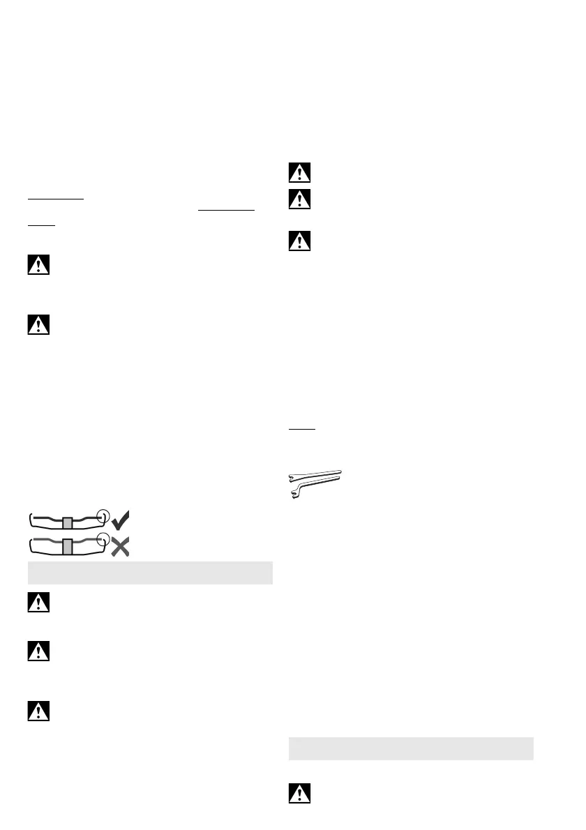
! In this case, use the
clamping nut (18) with 2-
hole spanner (19).
- Lock the spindle (see chapter 7.1).
- Flip up the clip
(1)
on the clamping nut.
- Fit the clamping nut (2) on the spindle (4). See
illustration D on page 2.
-
(1)Tighten the
clamping nut on the clip manually
in a clockwise direction.
- Flip down the clip
(1) again
.
To release the (tool-free) clamping nut (2)
:
- Lock the spindle (see chapter 7.1).
- Flip up the clip
(1)
on the clamping nut.
- Unscrew the clamping nut
(2)
, turning it anticlock-
wise manually .
Note:
If the clamping nut is very tightly secured
(2),
you can also use a 2-hole spanner
to unscrew it.
7.4 Tightening/loosening the clamping nut
Securing the clamping nut (18):
The 2 sides of the clamping nut are different. Screw
the clamping nut onto the spindle as follows:
See illustration D on page 2.
- A) For thin grinding wheels:
The edge of the clamping nut (18) faces upwards
so that the thin grinding wheel can be attached
securely.
B) For thick grinding wheels:
The edge of the clamping nut (18) faces down-
wards so that the clamping nut can be attached
securely to the spindle.
- Lock the spindle. Turn the clamping nut (18)
clockwise using the 2-hole spanner (19) to
secure.
Releasing the clamping nut:
- Lock the spindle (see chapter 7.1). Turn the
clamping nut (18) anticlockwise using the 2-hole
spanner (19) to unscrew.
8.1 Switching On and Off
Always guide the machine with both hands.
7. Attaching the grinding wheel
8. Use
 Loading...