30 Wattmeters
3.4.3 Apparent power measurements
1. Press the ON/OFF key: the first screen appears
2. Connect the measurement leads to the instrument’s current measurement terminals
(on the left), complying with the polarities indicated: red lead on the “+” terminal and
black lead on the “COM” terminal.
Connect the measurement leads to the instrument’s voltage measurement terminals
(on the right), complying with the polarities indicated: red lead on the “+” terminal
and black lead on the “COM” terminal.
3. Set up as indicated in the connection diagrams in Fig.4.4.1 (single phase) or Fig.4.4.2
(balanced three-phase, T3FE only PX 120), depending on the case, making sure if
possible that the maximum acceptable limits are not exceeded (see table below).
Range switching is automatic.
4. The upper digital display indicates the value of the voltage and the corresponding unit (V).
The middle digital display indicates the value of the current and the corresponding unit (A).
The lower digital display indicates the active power (W)
Press the DISPLAY key to display the 2nd screen:
The middle digital display indicates the value of the apparent power and the
corresponding unit (VA).
■■
■■
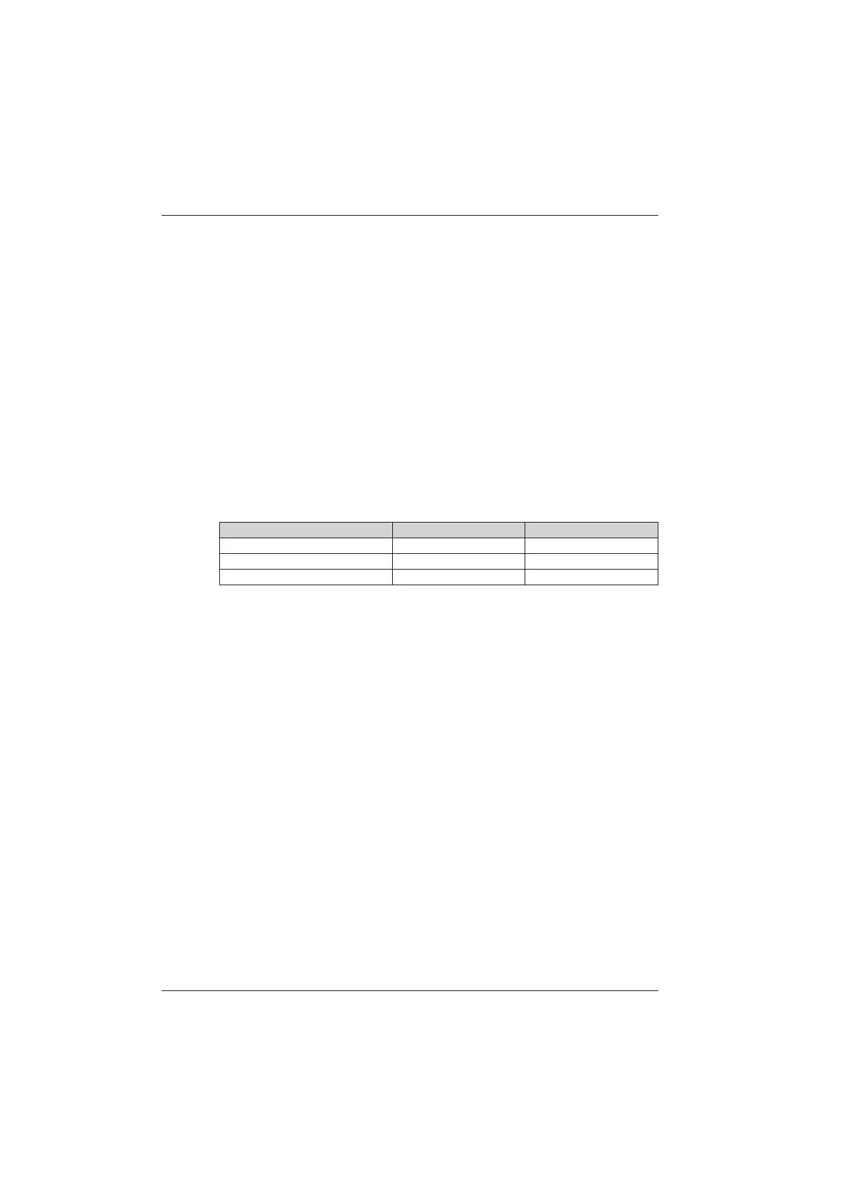
■ Characteristics
Display range 1000 VA 6 kVA
Measuring range 10.0 VA...999.9 VA 1000 VA...5999 kVA
Accuracy at 50 Hz 1,5% of reading ±2 cts 1% of reading ±2 cts
Resolution 0.1 VA 1 VA
3.4.4 Reactive power measurements
1. Press the ON/OFF key: the first screen appears.
2. Connect the measurement leads to the instrument’s current measurement terminals
(on the left), complying with the polarities indicated: red lead on the “+” terminal and
black lead on the “COM” terminal.
Connect the measurement leads to the instrument’s voltage measurement terminals
(on the right), complying with the polarities indicated: red lead on the “+” terminal
and black lead on the “COM” terminal.
3. Set up as indicated in the connection diagrams in Fig.4.4.1 (single phase) or Fig.4.4.2
(balanced three-phase, T3FE only PX 120), depending on the case, making sure if
possible that the maximum acceptable limits are not exceeded (see table below).
Range switching is automatic.
4. The upper digital display indicates the value of the voltage and the corresponding
unit (V).
The middle digital display indicates the value of the current and the corresponding
unit (A).
The lower digital display indicates the active power (W)
Press the DISPLAY key to display the 2nd screen:
- the upper digital display indicates the value of the reactive power and the
corresponding unit (VAR).
Chapter III
北京海洋兴业科技股份有限公司(证券代码:839145)

 Loading...