EasyManua.ls Logo

metso automation neles NP726 User Manual

Default Icon
20 pages
To Next Page IconTo Next Page
To Previous Page IconTo Previous Page
Page #9 background image
4.2 Pilot valve
Removal of the pilot valve is unnecessary when the changeover
piece is turned around. For instructions of removal, see Section 8.2.
4.3 Position of the cam plate
Choose the side, A or B, and the rising segment of the cam plate from
Fig. 4 in accordance with the function desired.
Move the actuator piston to the end where the input signal has its
lower value. Shut off the supply pressure or move the pilot spool
by deflecting the beam (5) gently so that the piston strokes to the
desired limit. The input signal should be zero or at the lower limit.
Loosen the screw (57), remove the indicator (32), loosen the screw (31)
and the locking wheel (30). Turn the cam plate (46) to the desired side.
In case of α
0
adjustment proceed acc. to Sections 6.1 and 6.2
Place the roller so that its contact point is 1 mm (0.04") from the beginning of
the rising segment. Then tighten the locking wheel (30) and the screw (31).
5 BASIC ADJUSTMENT
Basic adjustment is made to rotary and butterfly valves.
Please note the procedures in Chapter 4 before the adjustment.
1. Switch on the supply pressure (S) and the input signal (IN).
2. Set the input signal at the closed limit of the valve so that it
is 2 % i.e. 0.02 bar (0.2 psig) higher or lower than the limit value,
e.g. 0.2 + 0.02 = 0.22 bar (3 + 0.2 = 3.2 psig) or 1.0 - 0.02 = 0.98 bar
(15 - 0.2 = 14.8 psig). Loosen the screw (56). Turn the zero
adjustment screw (67) so that the actuator comes slowly to the
closed limit. Tighten the screw (56) always after the zero
adjustment. The valve should open slightly with a 4 % change in
signal, that is 0.03 bar (0.5 psig), e.g. 0.2 + 0.03 = 0.23 bar (3 +
0.5 = 3.5 psig) or 1.0 - 0.03 = 0.97 bar (15 - 0.5 = 14.5 psig).
See Figures 10 and 11.
3. Set the input signal to the other limit value. The valve should be
entirely open at 100 %, i.e. 1.0 bar (15 psig) or 0.2 bar (3 psig).
The valve should start to operate to closed direction at 98 %,
i.e. 0.98 bar (14.0 psig) or 0.22 bar (3.2 psig).
The range, i.e. turning angle, changes when the effective lenght
of the spring (60) is increased or decreased by turning the range
adjustment nut (60.3). See Fig. 11.
4. The zero and range adjustments affect each other, so stages 2
and 3 must be repeated a few times.
5. Screw on the pointer (32) into place so that the yellow line is in
the direction of the valve closing member. Tighten the screw (57).
6
α
0
-ADJUSTMENT
α
0
adjustment is made to segment and ball valves. This adjustment
takes into account the "dead angle" α
0
of the ball valve. The entire
signal range is then used for effective valve opening 90°-α
0,
see
Figure 12.
The same adjustment method can be applied to butterfly valves in
papermills for pulp flow control to avoid the dewatering of the pulp
near the closed position of the disc.
Table 3 shows the shift on the circumference of the cam equal to the
"dead angle" of the valve, Figure 13, in various cam segments (C, E, D).
Please note the procedures in Chapter 4 before the adjustment.
1. Mark the shift in question on the edge of the cam, Fig. 13 and
Table 3. Dimensions do not have to be measured if the dead angle
can be reliably noticed from position of the closing member.
2. Lock the cam plate (29) so that the roller touches the edge of the
cam at the mark. Tighten the locking wheel (30) and the screw (31).
3. Switch on the supply pressure (S) and the input signal (IN).
Rising input signal opens valve
Rising input signal closes valve
max 2 %
α
0
safety range 2 %
α
0
α
0
adjustmentBasic adjustment
INPUT SIGNAL %
POSITION %
Fig. 10.
Basic and α
0
adjustments
range
adjustment (60.3)
zero adjustment
(67)
screw (56)
range decreases
range increases
Fig. 11. Zero and range adjustments
α
0
= dead angle
Fig. 12. Dead angle
9
Question and Answer IconNeed help?

Do you have a question about the metso automation neles NP726 and is the answer not in the manual?

metso automation neles NP726 Specifications

General IconGeneral
Output SignalPneumatic
Supply Pressure1.4 - 7 bar (20 - 100 psi)
Temperature Range-40°C to +85°C (-40°F to +185°F)
Enclosure RatingNEMA 4X, IP66
Housing MaterialAluminum

Summary

1 INTRODUCTION

1.1 General

Basic information on the positioner.

1.2 Operating principle

Explains the force balance principle of operation.

1.3 Marking of positioner

Describes the ID plate and its information.

1.4 Technical specifications

Lists key technical parameters like signal ranges and pressures.

1.5 Approvals

Lists certifications like CENELEC, CSA, FM.

1.6 Recycling and disposal of a rejected positioner

Guidelines for recycling and disposal.

1.7 Safety precautions

Important safety warnings and cautions.

2 MOUNTING ON THE METSO AUTOMATION ACTUATOR

2.1 General

General notes on mounting positioners with actuators.

2.3 Installing positioner NP700/S2 on Metso Automation Series B actuators

Steps for mounting S2 positioner on Series B actuators.

2.4 NP_700/700 positioner/limit switch combination

Instructions for combining positioner with limit switch.

2.5 Piping of supply and signal air

Guidance on connecting air supply and signal lines.

3 INPUT SIGNAL AND DIRECTIONS OF OPERATION

3.1 Changeover piece

Explains the function and setting of the changeover piece.

3.2 Cam plate

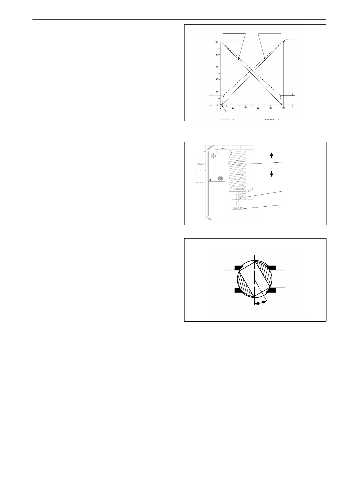
Describes the cam plate markings and signal ranges.

4 PRELIMINARY ACTIONS FOR THE ADJUSTMENT

4.1 Position of the changeover piece

Steps for setting the changeover piece position.

4.2 Pilot valve

Notes on the pilot valve, removal unnecessary for changeover.

4.3 Position of the cam plate

Steps for setting the cam plate position.

5 BASIC ADJUSTMENT

Basic Adjustment Steps

Detailed steps for performing basic adjustment.

6 α0-ADJUSTMENT

α0-ADJUSTMENT

Explains adjustment for ball valves considering 'dead angle'.

7 SPLIT-RANGE ADJUSTMENT

SPLIT-RANGE ADJUSTMENT

Method for split range adjustments using cam plate.

8 MAINTENANCE

8.1 Supply air filter

Maintenance of the supply air filter.

8.2 Pilot valve

Instructions for pilot valve removal and cleaning.

8.3 Replacement of the diaphragm

Steps for replacing the diaphragm.

9 TROUBLE SHOOTING

TROUBLE SHOOTING

Lists common problems and their potential causes.

10 OPTIONS

10.1 NP700/B and NP700/B1

Options for flameproof enclosure I/P converter.

10.2 NP700/GN natural gas construction

Natural gas construction details.

10.3 NP700/R dust-proof construction (IP 65)

Dust-proof construction details.

10.4 NP700/A with pressure gauges

Option for positioners with pressure gauges.

11 TOOLS

TOOLS

Equipment needed for adjustments.

12 ORDERING SPARE PARTS

ORDERING SPARE PARTS

Information required for ordering spare parts.

13 DRAWINGS AND PARTS LISTS

13.1 Exploded view and parts list

Detailed exploded view and parts list.

13.2 Mounting parts for B1C6-502 and B1J8-322 actuators (S1)

Lists mounting parts for specific actuators.

13.3 Mounting parts for Quadra-Powr actuators (S1)

Lists mounting parts for Quadra-Powr actuators.

13.4 Mounting parts for B1C6-20 and B1J8-20 actuators (S2)

Lists mounting parts for specific actuators.

13.5 Mounting parts for B1C25-502 and B1J25-322 actuators (S2)

Lists mounting parts for specific actuators.

14 TYPE CODE

TYPE CODE

Explains the product type code structure and options.

Related product manuals