7 NE 72 en 11
4. Set the input signal at the closed limit of the valve so
that it is 2 % i.e. 0.3 mA higher or lower than the limit
value, (e.g. 4 + 0.3 = 4.3 mA or 20 - 0.3 = 19.7 mA). Turn
the zero adjustment nut (61) with a screwdriver or fin-
gers so that the actuator comes slowly to the closed
limit. The valve should open slightly with a 4 % change
in signal, that is 0.6 mA, (e.g. 4 + 0.6 = 4.6 mA or 20 - 0.6
= 19.4 mA). See Figure 13.
5. Set the input signal to the other limit value. The valve
should be entirely open at 100 %, i.e. 20 mA or at 0 %, i.e.
4 mA. The valve should start to operate to closed direc-
tion at 98 %, i.e. 19.7 mA or 4.3 mA.
The range (turning angle) increases by turning the
range adjustment potentiometer (35.6) counterclock-
wise and decreases by turning clockwise.
6. The zero and range adjustments affect each other, so
stages 4 and 5 must be repeated a few times.
7. Screw on the pointer (32) into place so that the yellow
line is in the direction of the valve closing member.
Tighten the screw (57).
7 SPLIT-RANGE ADJUSTMENT
In principle, split range adjustments are made in the same
manner as for a normal signal range. Select a split range, 4–
12 mA or 12–20 mA, from the cam plate. See Figure 9.
8 MAINTENANCE
Regular maintenance is not necessary.
The need for maintenance depends on the quality of the
instrument air. See also Section 2.5.
If there is need for servicing proceed according to the fol-
lowing sections.
8.1 Supply air filter
The supply air filter (50) is located in the supply air connec-
tion (S); the filter can be removed for cleaning.
8.2 Pilot valve
Remove the pilot valve (44) by first loosening the nuts (49),
and then by lifting off the protective plate (48), the change-
over piece (46) and the gasket (45).
The pilot valve spool (44.2) should slip easily in the pilot
valve body (44.1).
If the pilot valve sticks, wash the body and spool with sol-
vent.
See the exploded view for the correct installation position
of the pilot valve. The size code for the pilot valve on the
body, for example DIA 4.0, must be visible on the right side.
Check the condition of the O-rings (43 and 47) and of the
gasket (45). The end of the leaf spring on the beam must be
on top of the pilot valve spool (Figure 13). Make sure that
the end of the beam (5) goes into the spool groove without
sideways deflections. After tightening the nuts (49), check
the beam once again by hand to see that the pilot valve
moves readily.
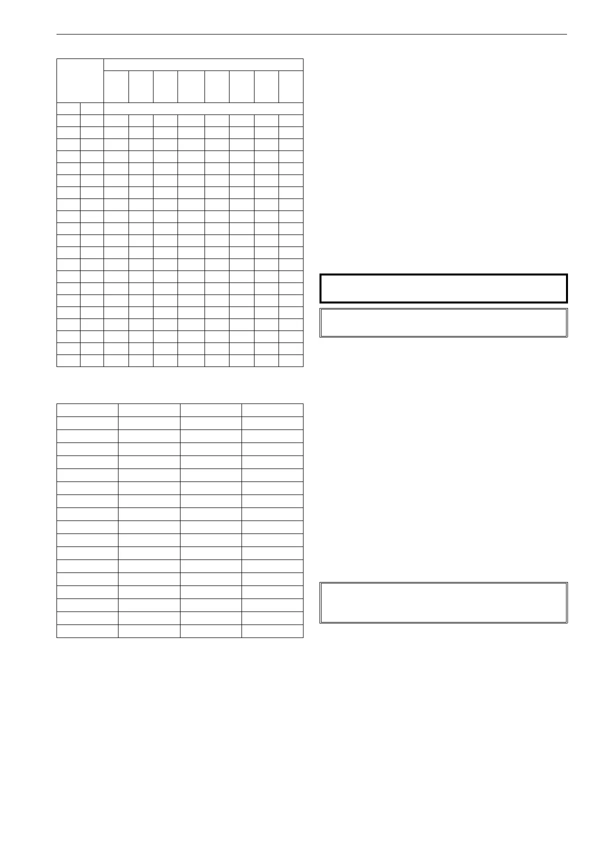
Table 4 Dead angle in degrees
Valve
size
Valve series
MBV
QMBV
1)
MBV
QMBV
2)
D
3)
T5,
QT5
QXT5
T25,
QT25
QXT25
R,
QR
mm mm Dead angle in degrees
25 1 12.5 - - 23.0 17.5 - - 14
40 1 1/2 11.0 - - 22.0 11.0 - - 11
50 2 9.0 8.0 12.0 22.0 11.0 16.0 7.0 15
65 2 1/2 8.0 - - - - - - 11
80 3 9.0 7.0 11.0 16.0 7.0 15.0 8.0 8
100 4 9.0 7.0 11.0 15.0 7.5 14.5 8.0 7
125 5 11.0 - - - - 11.0 6.0 7
150 6 9.0 7.0 10.5 14.5 8.0 12.0 7
200 8 8.0 6.5 7.5 11.0 6.0 8.5 6
250 10 8.0 6.5 7.0 12.0 8.5 6
300 12 7.0 5.5 5.5 8.5 7.0 5
350 14 5.4 5.5 - 4
400 16 4.5 5.0 8.S (14") 4
450 18 5.0 7.0 (16")
500 20 5.5
600 24 5.0
650 26 6.0
700 28 6.0
750 30 5.5
800 32 -
900 36 4.5
1) Seat supported 2) Trunnion 3) S/G seat
Table 5 Shift caused by dead angle, mm/inch
α
0
Segment C Segment E Segment D
20° *) 6.1/0.24 8.1/0.31
19° *) 5.8/0.22 7.7/0.30
18° *) 5.5/0.21 7.3/0.28
17° *) 5.2/0.20 6.9/0.27
16° *) 4.9/0.19 6.5/0.25
15° 3.1/0.12 4.6/0.18 6.1/0.24
14° 2.9/0.11 4.3/0.16 5.7/0.22
13° 2.7/0.10 4.0/0.15 5.3/0.20
12° 2.5/0.09 3.7/0.14 4.9/0.19
11° 2.3/0.09 3.4/0.13 4.5/0.17
10° 2.1/0.08 3.1/0.12 4.1/0.16
9° 1.9/0.07 2.8/0.11 3.7/0.14
8° 1.7/0.06 2.5/0.09 3.3/0.12
7° 1.5/0.05 2.2/0.08 2.9/0.11
6° 1.3/0.05 1.9/0.07 2.5/0.09
5° 1.1/0.04 1.6/0.06 2.1/0.08
4° 0.9/0.03 1.3/0.05 1.7/0.06
*) Segment C: α
0
max. 15°
CAUTION:
Do not dismantle a pressurized positioner!
NOTE:
Ensure the cleanness of the air piping.
NOTE:
The pilot valve body and spool constitute a pair, and must
not be replaced separately.
 Loading...