EasyManua.ls Logo

MG Midget User Manual

MG Midget
81 pages
To Next Page IconTo Next Page
To Previous Page IconTo Previous Page
Page #27 background imageLoading...
Page #27 background image
the distributor cover.
011
removing the distributor cover the position of the
metal electrode on the end of the distributor rotating arm can be seen, and
its position relat ve to this stud noted. That the pistons are exactly
at
the
top of their travel can he ascertained by removing the rectangular plate vn
the clutch housing (just in front of the gear lever), when a rn;~rk will be found
on the face of the flywheel, hearing the numbers
114.
This mark should be
exactly in the centre of the opening in the clutch housing.
Having made sure that the pistons and camshaft are in their correct
positions, the head may be lowered into position on to the cylinder block.
The two holes in
the flexible coupling should now coincide with those on the
drive yoke of the dynamo. Replace the ten cylinder head nuts and tighten
them up in the rotation indicated
in
the illustration, giving each a quarter
of
a
turn at a time until all are up tight.
Indicating the sequence in which the cylinder head stud
nuts
shoultl
gradually be tightened.
The flexible coupling bolts should now be
replaced,
as should the oil
pipes, exhaust and inlet manifolds, carburetter controls, petrol pipe, wind-
screen wiper tubing, sparking plugs, high tension cables, and the valve cover.
When replacing the oil pipe on the left hand side of the head, make sure
that
th,e oil restrictor pin is in place and that it is cle:~n.
Fill
the radiator with water, start up the engine and let it run quietly
until it is thoroughly warm.
Then, switching off again, remove the valve
cover and
go over each of the cylinder head nuts in turn, giving each a final
tightening up. It will be found that now the engine is warm an extra half
turn or so can be given to each nut. Do not attempt to speed
LIP
th'e engine
until this final tightening has been effected. Start up the engine and ascertain
that oil is exuding from the small oil passage drilled
in
each rocker-arm, and
lubricating the cam surfaces.
If
oil is coming freely from these oil passages,
the valve cover can be replaced, together with the bonnet, and the car is
ready for the road.
About
100
miles after the wlinder head repl:~cement, it is advisable to
go over the cylinder head nuts once again (when the engine is warm) to
ensure that they are absolutely tight, and nlso check the valve rocker clear-
ances (see below).
Rocker Clearance.
'The good tune
of
engines in frequently spoilt through
the owner seeking silence hy cutting down the rocker clearance.
In order to
maintain good tune over long periods it is advisable to set the rocker clear-
ance one or even two thousandths more than the amount indicated above.
This may incrcasc the calile goar ~loisc
hilt
wd1
z~ndozlhtedly lead to imfirovcd
maintenallcc of tune ocer lengthy ficriotis.
PAGE
TWENTY
D/I
Question and Answer IconNeed help?

Do you have a question about the MG Midget and is the answer not in the manual?

MG Midget Specifications

General IconGeneral
BrandMG
ModelMidget
CategoryAutomobile
LanguageEnglish

Summary

FOREWORD

CHASSIS AND DRIVETRAIN SYSTEMS

General Survey

Overview of the chassis, its components, and general mechanical details.

Lubrication

Guidance on oils and greases for various car components.

Gearbox and Back Axle

Oil recommendations and maintenance for gearbox and rear axle.

Steering

Explanation of the steering layout, design, and lubrication.

Brakes

Detailed information on the brake system, application, and adjustments.

Independent Adjustment

How to adjust brakes individually for each wheel.

Clutch

Operation, adjustment, and maintenance of the clutch system.

Shock Absorbers

Instructions for adjusting and maintaining shock absorbers.

ENGINE MAINTENANCE AND REPAIR

Decarbonising

Details the process of removing carbon deposits from the engine.

Valve Maintenance

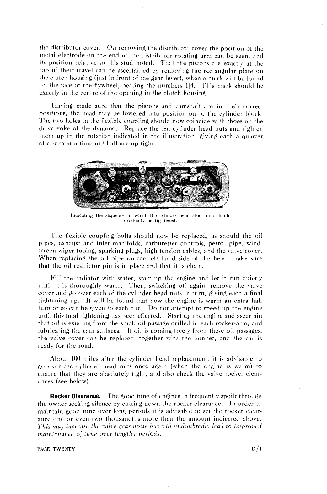
Instructions for removing, grinding, and reassembling engine valves.

Engine Bearings

Information regarding the care and maintenance of engine bearings.

IGNITION AND ELECTRICAL SYSTEMS

Ignition

Details on the distributor, coil, and associated components.

The Detection and Remedy of Ignition Faults

Troubleshooting guide for ignition failures and misfiring.

Headlamps

Information on headlamp adjustment, wiring, and cleaning.

Lucas Altette Horn (Type HF318)

Maintenance and troubleshooting for the car's electric horn.

The S.U. Petrol Pump

Operation, troubleshooting, and maintenance of the S.U. petrol pump.

CARBURATION

Carburetter

Explanation of the carburettor's function and components.

Adjusting

Steps for adjusting the carburettor for optimal engine performance.

Sources of Trouble

Common issues affecting carburettor function and their remedies.

BODY AND CHASSIS DETAILS

Body Hints

Advice on body maintenance, door adjustments, and access points.

Petrol Tank

Location and access to the car's fuel tank.

Luggage Platform

Details on the folding luggage platform and its operation.

The Spare Wheel

Information on the location and mounting of the spare wheel.

Bonnet Fasteners

Instructions for operating and securing the bonnet fasteners.

Tyres

Guidance on tyre maintenance, pressure checks, and fitting.

SERVICE AND AGENTS

LUCAS-C.A.V.-ROTAX SERVICE DEPOTS

List of service centres for electrical and related equipment.

Main and Sub-Agents

Directory of authorised service and sales agents across regions.

Related product manuals