Quick Start Guide 1110 DM16/DM12
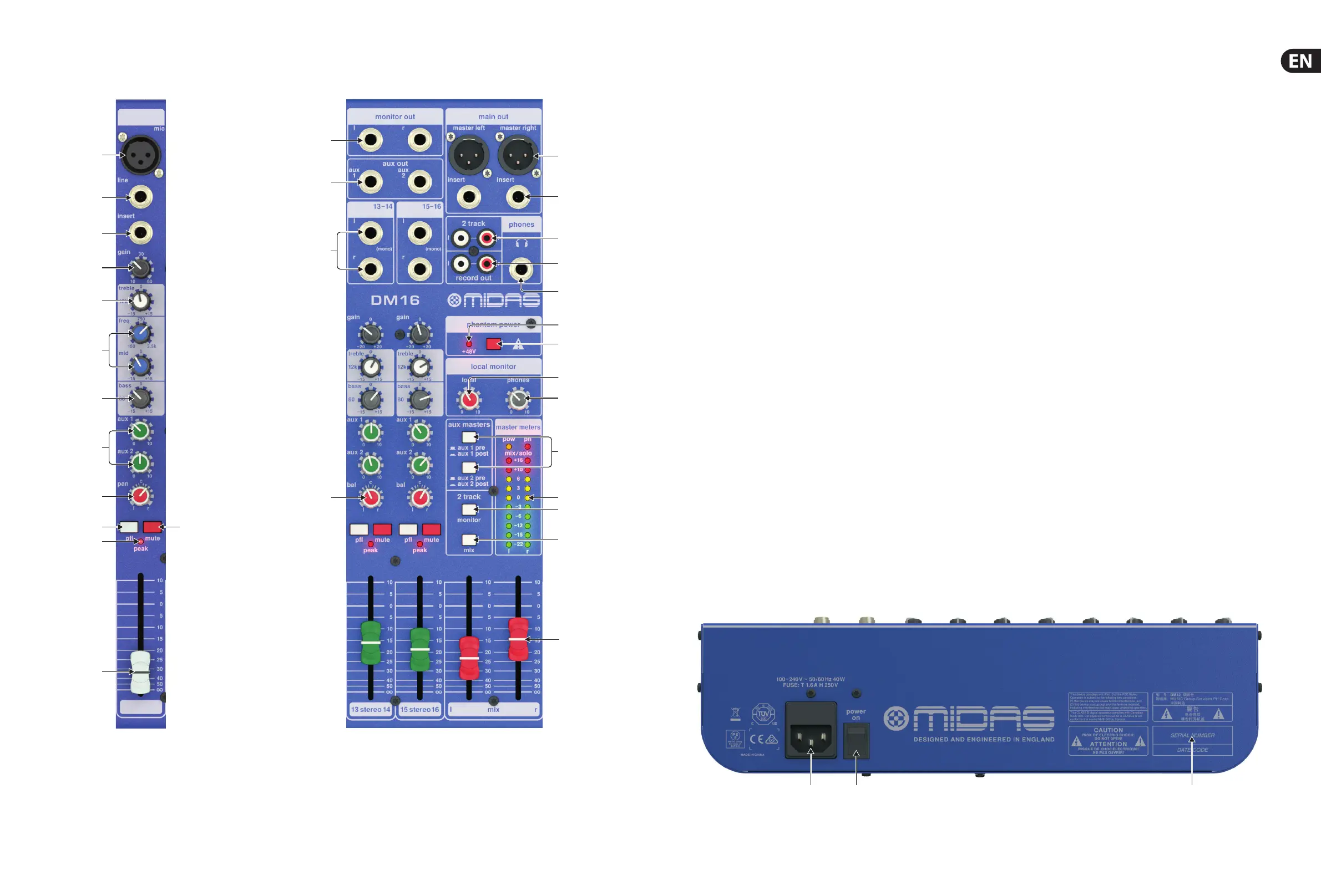
3. Top Panel
(1) MIC input connects microphones and other balanced signals using
XLR connectors.
(2) LINE input uses a ¼" TRS plug to connect either balanced or line-level
unbalanced signals.
(3) INSERT jack uses a ¼" TRS plug to bring external e ects processing
(typically compression) into the channel’s signal path. This jack requires
specialised insert cables that split into two plugs (either ¼ " TS or XLR) to
access the external unit’s in and out connections.
(4) GAIN knob adjusts the sensitivity of the MIC and/or LINE inputs.
(5) TREBLE knob adjusts the high frequencies.
(6) MID and FREQ knobs adjust midrange frequencies. Adjust the FREQ knob to
select the speci c frequency adjusted by the MID knob.
(7) BASS knob adjusts the low frequencies.
(8) AUX 1 and AUX 2 knobs controls the amount of signal sent from each
channel to the AUX OUT jacks for monitoring or external e ects processing.
Use the AUX MASTERS buttons to control whether the AUX channels send a
pre-fader signal (PRE) or a post-fader signal (POST).
(9) PAN knobs control the left-right stereo placement for each channel.
(10) PFL (Pre Fader Listen) button, when pressed, solos the channel and
sends the input signal to the MASTER METERS section for more precise
gain-setting. In PFL mode, the soloed signal routes to the MONITOR OUT
and PHONES outputs, and the PFL LED in the MASTER METERS section will
light up.
(11) PEAK LED lights when the channel signal overloads.
(12) MUTE button mutes the channel.
(13) CHANNEL FADERS control the nal level for each channel within the
overall mix.
(14) BAL knob controls the relative left-right balance for stereo signals coming in
through the STEREO 1 and STEREO 2 inputs.
(15) STEREO 1 and STEREO 2 inputs can be used to route left-right stereo
signals into the mix, such as stereo returns from external e ects processors.
For mono signals, use the L (MONO) input of each pair of stereo inputs.
(16) AUX OUT jacks can be used to route AUX mixes out to external e ects
processors or to stage monitors. For send-and-return e ects processing, use
the STEREO 1 and STEREO 2 inputs to route the e ected “wet” signals back
into the overall mix.
(17) MONITOR OUT jacks use ¼" TRS plugs to route a copy of the nal mix out
to local or studio monitors. Control the MONITOR OUT level by using the
LOCAL knob in the LOCAL MONITOR section. In PFL (Pre Fader Listen) mode,
the soloed PFL signal will override and replace the main mix signal in the
MONITOR OUT output.
(18) MASTER LEFT and MASTER RIGHT jacks use XLR connectors to send the nal
stereo mix out to monitors or the main house mix (live sound).
(19) MAIN OUT INSERT jacks use a ¼" TRS plugs to apply external e ects
processing to the nal mix before the signal goes out through the MASTER
outputs (e.g., to compress the entire nal mix). This jack requires specialised
insert cables that split into two plugs (either ¼ " TS or XLR) to access the
external processor’s in and out jacks.
(20) 2 TRACK uses RCA jacks to route an additional line-level stereo signal into
the main mix (MIX button) and/or the MONITOR OUT mix (MONITOR button).
Control the level of the 2 TRACK signal by using the volume control on your
stereo sound source.
(21) RECORD OUT uses RCA jacks to send a line-level copy of the nal mix signal
out to external recording devices.
(22) PHONES jack connects headphones using a ¼" TRS plug. Control the output
level by using the PHONES knob in the LOCAL MONITOR section. The PHONES
source signal comes from the main mix, except in PFL mode, when the
soloed PFL signal will override and replace the main mix signal.
(23) +48 V LED lights up to indicate that phantom power has been activated.
(24) PHANTOM POWER button turns phantom power on and o .
(25) LOCAL knob controls the output level for the MONITOR OUT jacks.
(26) PHONES knob controls the output level for the PHONES jack.
(27) AUX MASTERS buttons control the pre-fader (PRE) and post-fader (POST)
settings for the AUX 1 and AUX 2 knobs.
(28) MASTER METERS display levels for the main mix, as well as soloed channels
with the PFL (Pre-Fader Listen) function activated for detailed gain-setting.
The POW LED lights to indicate that the unit has been powered up. The PFL
LED lights up to indicate that the meter is being used for PFL gain setting.
(29) 2 TRACK MONITOR button routes the stereo 2 TRACK signal into the
MONITOR OUT mix.
(30) 2 TRACK MIX button routes the stereo 2 TRACK signal into the main mix.
(31) MIX faders adjust the overall output of the mixer at the MASTER LEFT and
MASTER RIGHT jacks.
4. Rear Panel
(32) AC IN accepts the included power cable for connection to a mains outlet.
(33) POWER ON switch turns the mixer on and o .
(34) SERIAL NUMBER for Warranty registration.
 Loading...