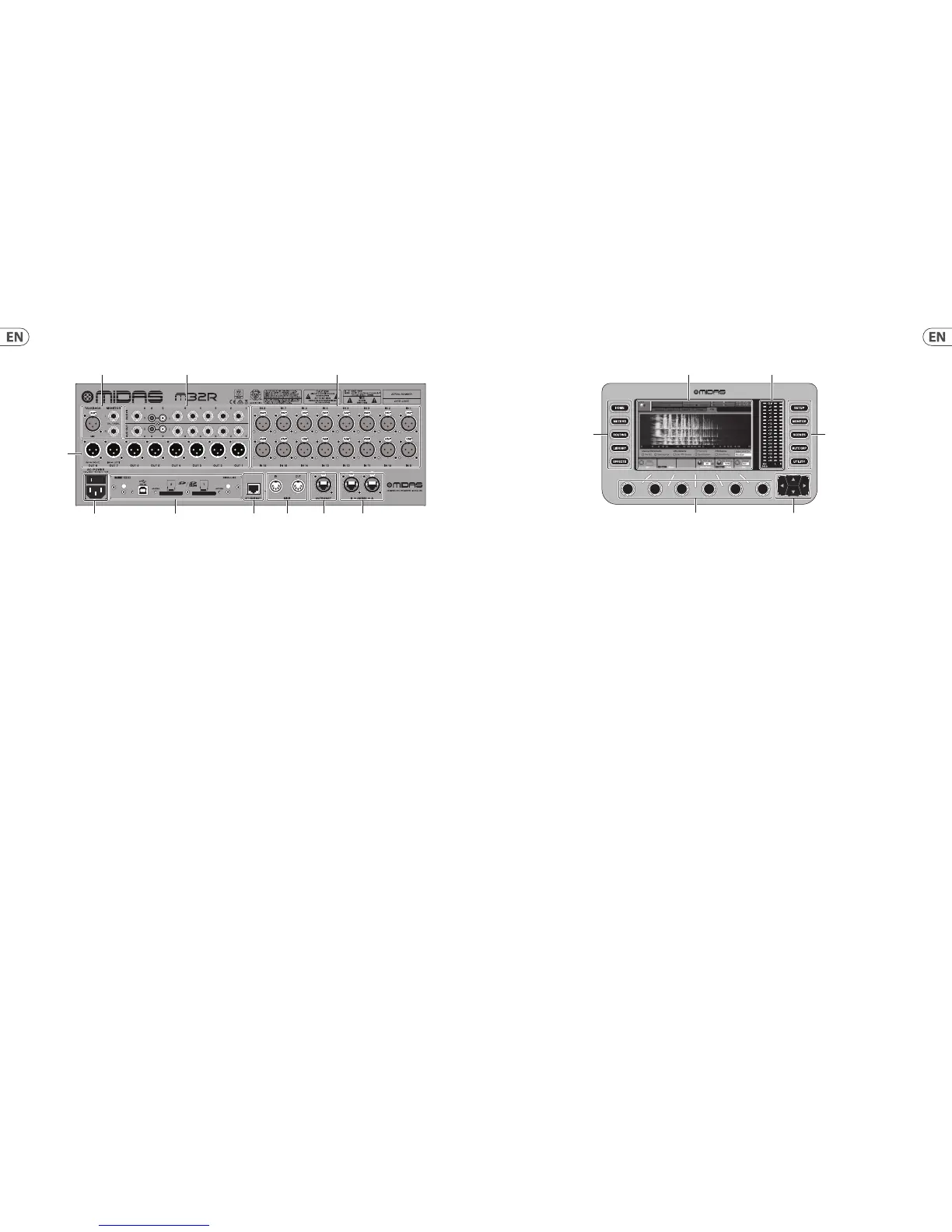
(1) MONITOR/CONTROL ROOM OUTPUTS
- connect a pair of studio monitors using
XLR or ¼" cables. Also includes a 12 V / 5 W
lamp connection.
(2) AUX IN/OUT - Connect to and from external
equipment via ¼" or RCA cables.
(3) INPUTS 1 - 16 - Connect audio sources
(such as microphones or line level sources)
via XLR cables.
(4) POWER - The IEC mains socket and
ON/OFF switch.
(5) OUTPUTS 1 - 8 - Send analogue audio
to external equipment using XLR cables.
Outputs 15 and 16 by default carry the main
stereo bus signals.
(6) DN32-LIVE INTERFACE CARD - Transmit up to
32 channels of audio to and from a computer
via USB 2.0, as well as record up to 32 channels
to SD/SDHC cards.
(7) REMOTE CONTROL INPUTS - Connect to a PC
for remote control via Ethernet cable.
(8) MIDI IN/OUT - Send and receive MIDI
commands via 5-pin DIN cables.
(9) ULTRANET - Connect to a personal
monitoring system, such as the BEHRINGER
P16, via Ethernet cable.
(10) AES50 A/B - Transmit up to 96 channels in
and out via Ethernet cables.
Please refer to the User Manual for more information
on each of these topics.
3. Main Display
(1) DISPLAY SCREEN - The controls in this section
are used in conjunction with the colour screen
in order to navigate and control the graphical
elements it contains.
By including dedicated rotary controls that
correspond to the adjacent controls on the
screen, as well as including cursor buttons,
the user can quickly navigate and control all of
the colour screen’s elements.
The colour screen contains various displays
that give visual feedback for the operation of
the console, and also allow the user to make
various adjustments not provided for by the
dedicated hardware controls.
(2) MAIN/SOLO METERS - This triple 24-segment
meter displays the audio signal level output
from the main bus, as well as the main centre
or solo bus of the console.
(3) SCREEN SELECTION BUTTONS - These
eight illuminated buttons allow the user to
immediately navigate to any of the eight
master screens that address di erent sections
of the console. The sections that can be
navigated are:
• • HOME - The HOME screen contains an
overview of the selected input or output
channel, and o ers various adjustments
not available through the dedicated top-
panel controls.
The HOME screen contains the following
separate tabs:
home: General signal path for the
selected input or output channel.
con g: Allows selection of the signal
source/destination for the channel,
con guration of insert point,
and other settings.
gate: Controls and displays the channel
gate e ect beyond those o ered by the
dedicated top-panel controls.
dyn: Dynamics - controls and displays the
channel dynamics e ect (compressor)
beyond those o ered by the dedicated
top-panel controls.
eq: Controls and displays the channel
EQ e ect beyond those o ered by the
dedicated top-panel controls.
sends: Controls and displays for channel
sends, such as sends metering and
send muting.
main: Controls and displays for the
selected channel’s output.
• • METERS - The meters screen displays
di erent groups of level meters for
various signal paths, and is useful for
quickly ascertaining if any channels need
level adjustment. Since there are no
parameters to adjust for the metering
displays, none of the metering screens
contain any ‘bottom of the screen’
controls that would normally be adjusted
by the six rotary controls.
The METER screen contains the following
separate screen tabs, each containing
level meters for the relevant signal paths:
channel, mix bus, aux/fx, in/out and rta.
• • ROUTING - The ROUTING screen is where
all signal patching is done, allowing the
user to route internal signal paths to
and from the physical input/output
connectors located on the console’s
rear panel.
The ROUTING screen contains the
following separate tabs:
home: Allows patching of physical inputs
to the 32 input channels and aux inputs of
the console.
out 1-16: Allows patching of internal
signal paths to the console’s 16 rear panel
XLR outputs.
aux out: Allows patching of internal
signal paths to the console’s six rear panel
¼" / RCA auxiliary outputs.
p16 out: Allows patching of internal signal
paths to the 16 outputs of the console’s
16-channel P16 ULTRANET output.
card out: Allows patching of internal
signal paths to the 32 outputs of the
expansion card.
aes50-a: Allows patching of internal
signal paths to the 48 outputs of the rear
panel AES50-A output.
aes50-b: Allows patching of internal
signal paths to the 48 outputs of the rear
panel AES50-B output.
xlr out: Allows the user to con gure the
XLR outs on the rear of the console in
blocks of four, from either local inputs,
the AES streams, or expansion card.
 Loading...