32801002001 Specifications subject to change without notice. 19
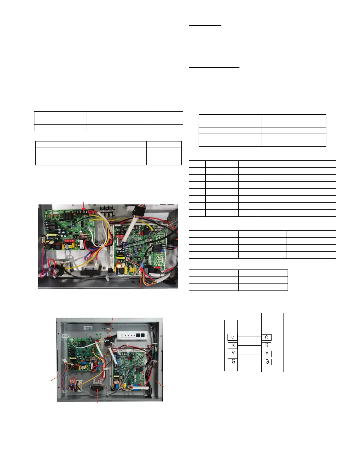
Step 9 - Third Party Thermostat Installation
The indoor unit has a 24V interface that provides flexibility,
functionality and control by a 3rd party thermostat* (field supplied).
1. Run the thermostat wiring from the thermostat to the 24V interface
using connection R and C on CN15 and Y, W, G on CN19. see Fig.
64.
2. The 24V Interface Dip Switches come pre-configured for normal
operation and easy installation. Dip Switch 2-1 can be configured to
make the system operate in the COOLING ONLY mode. Dip
Switch 3-1 can be configured for the DRY mode when not using
auxiliary heat.
Table 13 — DIP Switch 2-1
Table 14 — DIP Switch 3-1
3. Configure the thermostat to operate as a single stage cooling and
heating (DO NOT configure the thermostat as Heat Pump).
*A conventional 5-wire thermostat is required. A 2 Heat/ 1 Cool thermostat is
required for electric heat application.
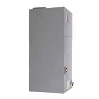
Fig. 59 — Indoor Unit Control Box Size 24
Fig. 60 — Indoor Unit Control Box Sizes 36 - 48
LED Display
The control displays active faults codes on the LED display. When the
control displays the fault code and the LED flashes quickly, there is
something wrong with the system. Refer to “TROUBLESHOOTING”
for the detailed fault codes.
Temperature Sensor
The unit has one temperature sensor, which is called a Pipe
Temperature Sensor. If the temperature sensor is damaged, the system
shuts down and the LED flashes repeatedly.
Connector
Table 15 — Connector
Table 16 — Mode Setting
Table 17 — Fan Speed Setting
Fig. 61 — Cooling Only System Wiring Diagram
SW2-1 RESULT NOTE
ON COOLING ONLY
OFF HEAT PUMP Default
SW3-1 RESULT NOTE
ON DRY Mode
OFF
Used on future
applications
Default
Main Terminal Board
Main
Board
24V
Interface
Board
24V Transformer
Connector Purpose
Y Cooling
W Heating
G Fan-Auto Speed
AUX/DRY Aux-Heat/Dry
Y W G AUX/DRY SETTING MODE
√ X * * Cooling
X √ * X Heating (without aux-heater)
X √ * √ Heating (with aux-heater)
XX√ X Fan only
√√** OFF
XXX X OFF
XX * √ Dry
UNIT ON/OFF G SETTING FAN SPEED
√ X Auto Fan Speed
√√Auto Fan Speed
X X Fan OFF
√ ON
XOFF
*ON or OFF
INDOOR UNIT OUTPUT WITH 24VAC 1.5A
INDOOR UNIT
 Loading...