DLFSAB and DLFLAB: Service Manual
Manufacturer reserves the right to change, at any time, specifications and designs without notice and without obligations.
21
Index:
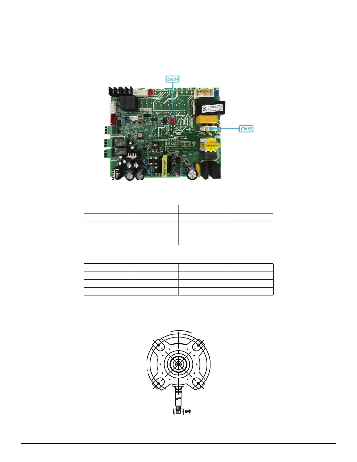
1. Indoor DC Fan Motor (control chip is on PCB)
Power on the unit and when the unit is in the STANDBY mode, measure the pin1&pin2 voltage of CN15, and pin3 of CN34 in the fan motor
connector. If the voltage value is not in the range shown in Table 12, the PCB has an issue and needs to be replaced.
Table 12 — CN34
Table 13 — CN15
2. Outdoor DC Fan Motor (control chip is in outdoor PCB)
Release the UVW connector. Measure the resistance of U-V, U-W, V-W. If the resistance is not equal to each other, the fan motor has an issue and
needs to be replaced. Otherwise the PCB has an issue and needs to be replaced.
Fig. 17 — Outdoor DC Fan Motor
NO. COLOR SIGNAL VOLTAGE
1/ /
2BlackGND
3 Orange PWM 5-12VDC
4BlueFG0-12DVC
NO. COLOR SIGNAL VOLTAGE
1 Yellow 208/230VAC
2 Black 208/230VAC
3 Yellow-Green GND
 Loading...