4. Table 5
Pipe size and connection of indoor unit
Liquid side
Gas side
F19.0 flaring nut 9.53 flaring nut
130m
150m
40m
50m
30m
15m
L1+L2+L3+L4+L5+L6
L1+L3+L4+L5+L6+i
L3+L4+L5+L6+i
+a+b+c+d+e+f+g+h+i
20HP
250m
300m
20HP
h 15m
L
1
L
2
L
3
L
4
L
5
L
6
a
b
c
d
e
f
g
h
i
1 Table 1
Pipe size and connection of outdoor unit
2 Table 2
3
12
Type of pipe
4 Table 4
Size of main pipe
A: Capacity of all the indoor units.
A(horsepower)
A12
12A16
16A24
24A32
32A48
48A64
F28.6/ F12.7
F38.0/ F19.0
F45.0/ F22.0
MDV-BY101
MDV-BY102(A) (refit)
MDV-BY102(A)
MDV-BY103(A)
Size of main pipe connecting multi-modules (unit: mm)
3 Table 3
F54.0/ F25.0
MDV-B Y104
4.Take 30HP outdoor unit for example:
1 a 2 b 3 c 4 d 5 e 6 f 13
7 8 9 10 11 12
#
1
7#
(5P) (5P) (5P) (5P) (3P) (2P)
5P
#
2
#
3
#
4
#
5
#
6
Determine pipe size
1. Branch pipes: No.7, 8, 9, 10,11, 12 and 13 the size is F19.0/F9.53
2. 6# and 7# indoor units connect with pipe 6, total HP is 2+5=7P 10P pipe size is
F28.6/F12.7, model of branch join: MDV-BY101
3. Subordinate indoor units of pipe 5 are :5#, 6# and 7#, total HP is 3+2+5=10P 10P,
pipe size is F28.6/ F12.7, model of branch joint: MDV-BY101
4. Subordinate indoor unis of pipe 4 are 4#, 5#, 6# and 7#, total HP is 5+3+2 +5=15P
16P, pipe size is F38.0/F15.9, model of branch joint:MDV-BY102(A)
5. Subordinate indoor units of pipe 3 are 3#, 4#, 5#, 6# and 7#, total HP is 5+5+3+2+5=
20P 24P, pipe size is F38.0/F19.0, model of branch joint:MDV-BY102(A)
6. Subordinate indoor units of pipe 2 are 2# 7#, totel HP is 5+5+5+3+2+5=25P 32P,
pipe size is F45.0/F22.0, model of branch joint:MDV-BY103(A)
7. Pipe 1 is main pipe, the size is F45.0/F22.0, model of branch joint: MDV-BY103(A)
MDV-BY105
f
9.53
f
12.7
0.065kg
0.115kg
f
19.0
f
22.0
0.290kg
0.380kg
f
25.0
0.580kg
f
15.9
0.190kg
f
28.6
0.760kg
F38.0/ F15.9
F67.0/ F28.6
NOTE: The size of T-shaped pipe X connecting with
oil pipe is the same with that specified in three modules.
The sizes of T-shaped pipes Y and Z connecting with
gas pipe are the same with that specified in three modules.
Liquid side
12.7(flaring nut)
12.7(flaring nut)
12.7(flaring nut)
15.9(flaring nut)
15.9(flaring nut)
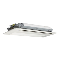
MDV-D400W/CS
MDV-D450W/CS
MDV-D335W/CS
MDV-D280W/CS
MDV-D252W/CS
Model
Gas side
28.6(welding)
28.6(welding)
28.6(welding)
38.0(welding)
38.0(welding)
Capacity of parallel unit A (HP) Pipe size (gas/liquid)
Name
Branch pipe
Main pipe
Pipe location
Directly connect to indoor unit
Not directly connect to indoor unit
Number in chart
Main pipe(gas side/liquid side) Branch joint
Note: Select the first branch joint based on the capacity of outdoor
unit, which should be larger than other branch joints.
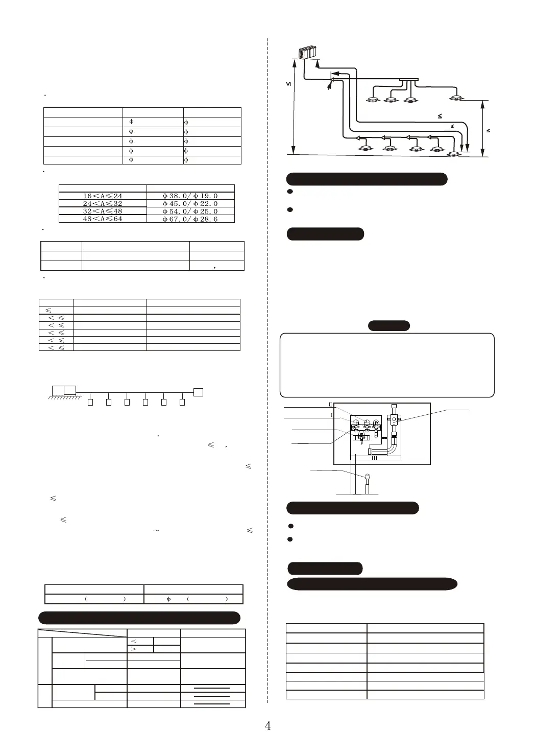
Length and Drop Height Permitted of the Refrigerant piping
Permitted value
Total Pipe Length (Actual)
Max Piping (L)
Indoor Unit to Indoor Unit Drop Height(h)
Indoor-Outdoor Unit
Drop Height(H)
Piping (farthest from the first line
pipe branch) Equivalent Length (l)
Actual Length
Equivalent Length
Outdoor Unit Up
Outdoor Unit Down
Pipe Length
Drop
Height
Piping
Outdoor Unit (one or more outdoor units)
Indoor Unit
Indoor Unit
Indoor Unit to Indoor Unit
Drop Height
Max Piping Equivalent Length L 125m
(From the first branch) Max piping Equivalent Length l 40m
Branch header
Drop Height between Indoor
unit and outdoor Unit H 50m
First branch
Make sure there is no any dirt or water before
connecting the piping to the outdoor units.
Wash the piping with high pressure nitrogen, never
use refrigerant of the outdoor unit.
Remove Dirt or Water in the Piping
Airtight Test
1. Connect piping on hi-pressure side with hi-pressure
valve. (For multi-modules parallel connection, please
connect gas and oil balance valves.)
2. Weld the piping on low-pressure side with gauge joint.
3. Charge nitrogen from hi-pressure valve core and gauge
joint.
4. After airtight test, weld low-pressure ball valve and
piping on low--pressure side.
CAUTION
2
1. Pressured nitrogen [2.94MPa (30kg/cm ) should be used in the
airtight test.
3. The airtight test should never use any oxygen, flammable gas
or poisonous gas.
2. Do not connect piping on low-pressure side and low-pressure ball
valve before charging nitrogen.
4. Wrap low-pressure valve and balance valves with wet cloth while welding.
Hi-pressure valve
Low-pressure ball valve
Gauge joint
Do vacuum with vacuum pump instead of refrigerant.
Vacuum with vacuum pump
Vacuuming should be done from liquid and gas side
simultaneously. The pressure should be lower than
30Pa.
Open all valves
Refrigerant Amount to be Added
Calculate the added refrigerant according to the diameter
and the length of the liquid side pipe of the ou tdoor/indoor
unit connection. The refrigerant is R22.
Pipe size on liquid side
Refrigerant to be Added per meter
Oil balance valve
Gas balance valve
Gas balance valve
Indoor unit and branch joint
 Loading...