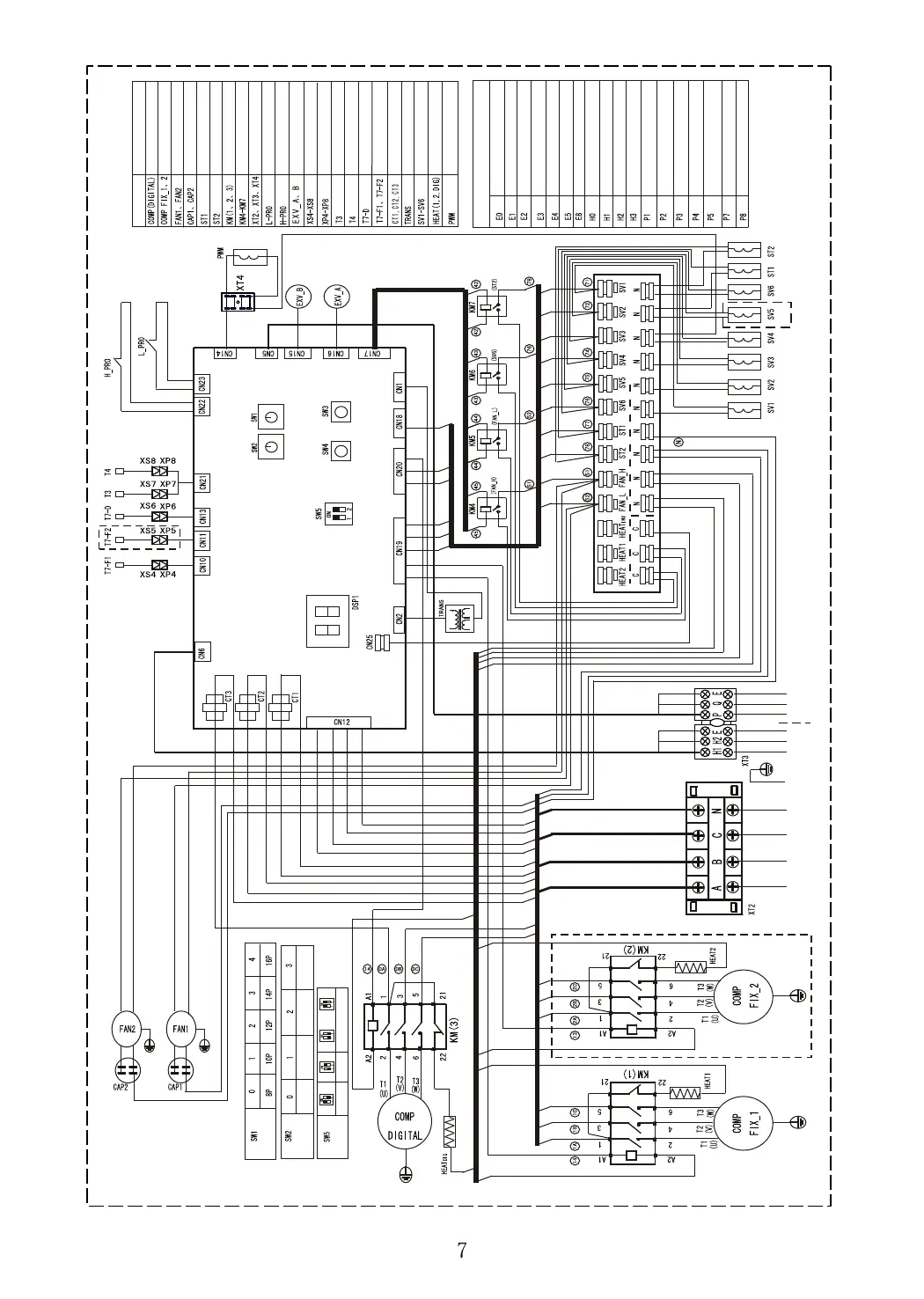
Main control board
Red
Red
Red
Red
Red
Red
Red
Red
Red
Black
White
Blue
Blue
Green
Yellow
Brown
Green
Yellow
Brown
Blue
Red
Red
White
White
Black
Red
Yellow
Yellow
Red
Black
Blue
Blue
Black
Black
Black
Blue
Blue
Blue
Blue
Blue
Blue
Red
White
Red
Red
White
White
Blue
Blue
Blue
Blue
Blue
Black
Black
Black
Black
Blue
Blue
Blue
Blue
Blue
Blue
Blue
Blue
Blue
Blue
Blue
Black
Red
White
Brown
Yellow
Green
Green
Yellow
Red
Black
White
Red
White
Blue
Blue
Black
Black
Black
Yellow/green
Yellow/green
White
Blue
Brown
Red
White
Red
Blue
Red
Black
Blue
Red
White
Red
Red
Red
Red
Red
Red
Black
White
Blue
Black
Yellow/green
Yellow/green
White
Blue
Yellow
Grey
Orange
Black
Black
Green
SW1 capacity setting (unchangeable)
Main unit
Auxiliary unit1
Auxiliary unit2 Auxiliary unit3
3-phase power supply
To outdoor COMM.
To indoor COMM.
(Load patch board)
CODE
Digital compressor
Fixed compressor
Capacitor, fan
Main 4-way valve
Relay
Contactor
Terminal
Low-pressure switch
Hi-pressue switch
Electronic expansion valve
Middle terminal
Middle terminal
Pipe temp sensor
Outdoor temp sensor
Current inductor
Solenoid valve
DSP1
Outdoor unit COMM error
Phase protection
COMM error with indoor unit
T3 pipe temp sensor errror
T4 outdoor temp sensor error
Discharge temp sensor error, digital compressor
Outdoor unit address error
Chip COMM error
Qty of outdoor unit decreases
Qty of outdoor unit increases
Hi-pressure protection
Low-pressure protection
Over-current protection, digital compressor
Compressor overhigh discharge temp protection
Outdoor condenser hi temp protection
Current protection, No.1 fixed compressor
Current protection, No.2 fixed compressor
Fan
Auxil. 4-way valve
Discharge temp sensor, digital compressor
Discharge temp sensor, fixed compressor
Power transformer
Crankcase heating
PWM unloading valve
COOL HEAT
or
AUTO (Default)
Mode setting
Black
Black
(Reserved)
Mode conflict
Yellow/green
Blue
White
Red
Red
Red
White
Blue
Black
Outdoor unit
wiring nameplate
Capacity setting
Address setting
NAME
 Loading...