V8 Mini R410A VRF 50Hz
87
Part 3 - System Design and Installation
6.1.5 Installation of joint insulation
Insulation at joints in the refrigerant piping should be installed after the gastightness test has been successfully completed.
The procedure at each joint is as follows:
1. Cut a section of insulation 50 to 100mm longer than the gap to be filled. Ensure that the cross-sectional and longitudinal
openings are all cut evenly.
2. Embed the section into the gap ensuring that the ends abut tightly to the sections of insulation either side of the gap.
3. Glue the longitudinal cut and the joints with the sections of insulation either side of the gap.
4. Seal the seams with tape.
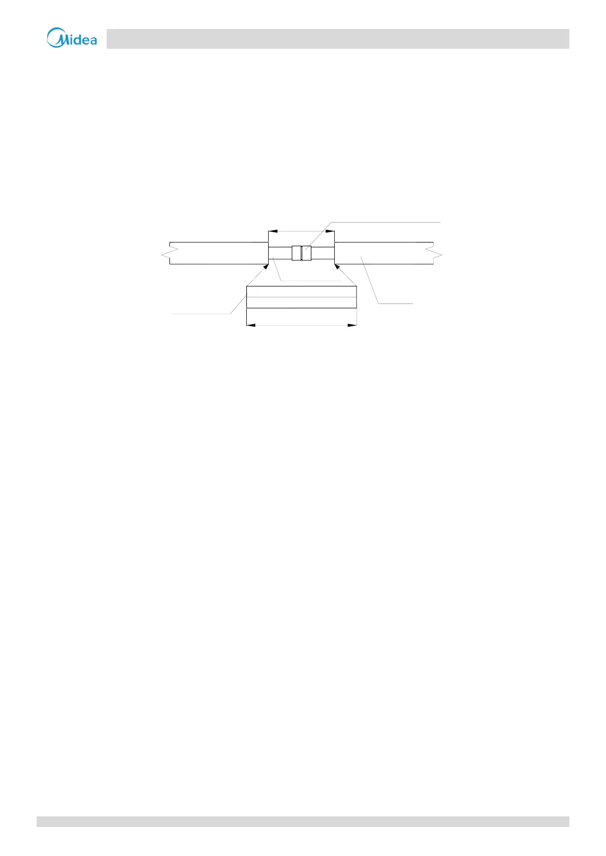
Figure 3-6.1: Installation of joint insulation (unit: mm)
Copper pipe
Insulation
material
400
300
straight-through joint
Insulation
material
6.2 Drain Piping Insulation
Use rubber/plastic insulating tube with a B1 fire resistance rating.
The insulation should typically be in excess of 10mm thick.
For drain piping installed inside a wall, insulation is not required.
Use suitable adhesive to seal seams and joints in the insulation and then bind with cloth reinforced tape of width not
less than 50mm. Ensure tape is fixed firmly to avoid condensation.
Ensure the drain piping insulation adjacent to the indoor unit drainage water outlet is fixed to the unit itself using
adhesive, to prevent condensation and dripping.
6.3 Ducting Insulation
Suitable insulation should be added to ducting in according with all applicable legislation.

 Loading...