V8 Mini R410A VRF 50Hz
91
Part 3 - System Design and Installation
Figure 3-8.1: Indoor unit unified power supply wiring
8.3 Communication Wiring
Communication wiring design and installation should adhere to the following requirements:
Do not connect the communication line when the power is on.
Connect the shielding nets at both ends of the shielded wire to the sheet metal “ ” of the electronic control box.
Do not connect the power cable to the terminal of communication line, otherwise, the motherboard will be damaged.
Do not connect a system with both HyperLink (M1 M2) communication lines and P Q communication lines.
On-site wiring must comply with the relevant regulations of the local Country/region and must be completed by
professionals.
The communication lines of the indoor and ODUs can only be connected from the outdoor unit.
When a single communication line is not long enough, the joint must be crimped or soldered, and the copper wire at
the joint shall not be exposed.
When use HyperLink, It is forbidden to reverse the connection of the two communication ports (to up IDU) and (to
down IDU) of the repeater.
V8 Mini outdoor unit compatible with different generation indoor units, the communication connection type should
follow table 3-8.1.
Leakage protector
Manual switch
Branch box
Indoor unit
1
9
2
10
3
11
4
12
5
13
6
14
7
15
8
16
Single-phase 220~ 50/60Hz
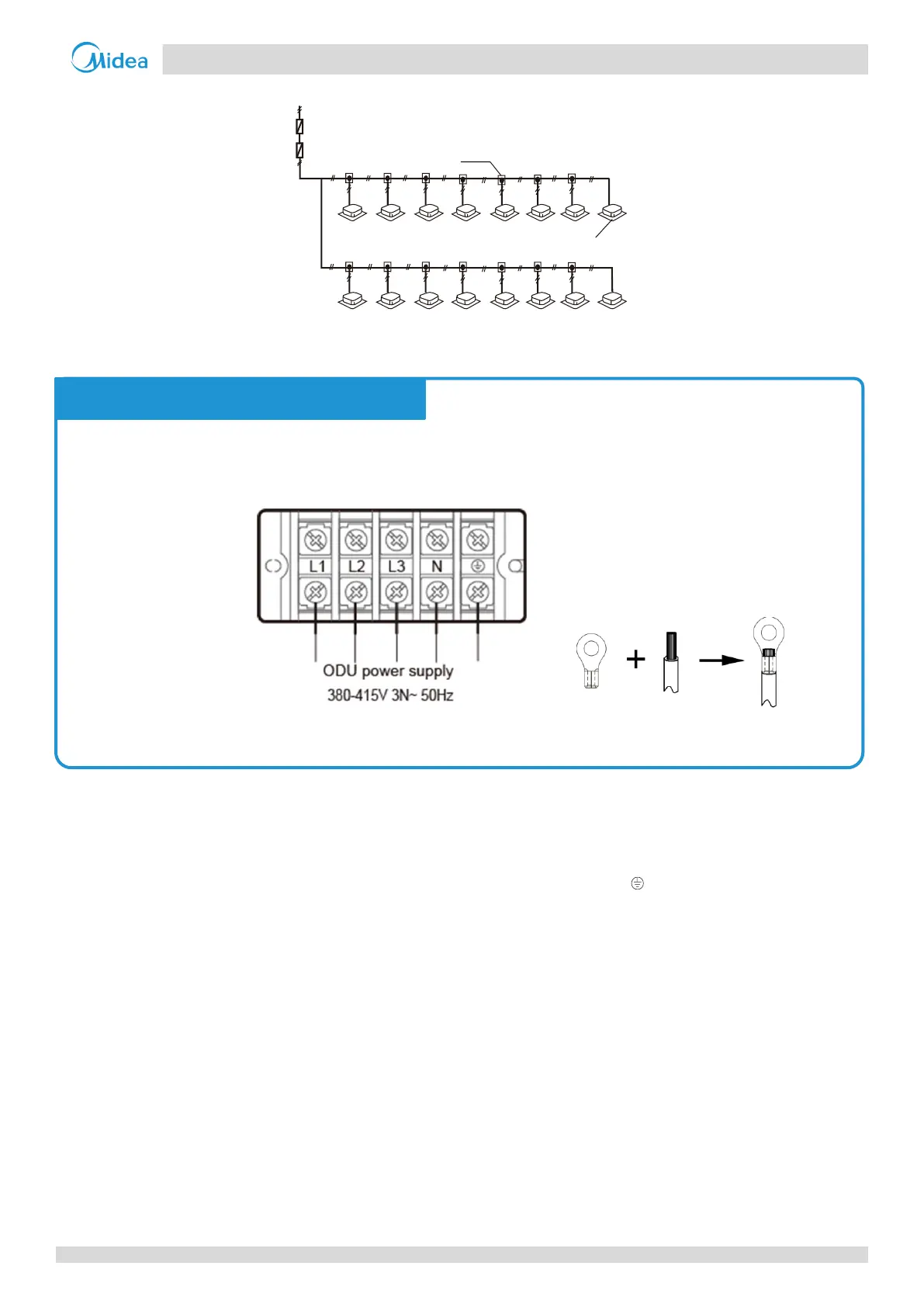
The 380-415V, 3N~, 50Hz power supply should be connected to the outdoor unit power supply terminals as shown in
Figure 3-8.2. Use round-type terminals of the correct specifications to connect the power cable.
Figure 3-8.2: Outdoor unit 3-phase power supply terminals

 Loading...