PWR LED is lit when the router is powered on.
The use of LEDs can be configured from RouterOS.
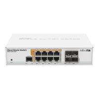
Triangle LEDs (top row) indicate PoE out status. Green LED indicates that the respective port uses low voltage, a red LED indicates high voltage.
Flashing single green LED: problem to start a low voltage device. Flashing single red LED: problem with high voltage device.
The square port LEDs (bottom row) indicate the individual Ethernet, SFP port activity.
FAN FAULT LED indicates a problem with any of the cooling fans.
PoE FAULT LED indicates an exceeded overall max PoE output limit. Port PoE-out priorities will work in 3 independent sections (8 ports each)
and overload will happen in any section that breach 150W consumption
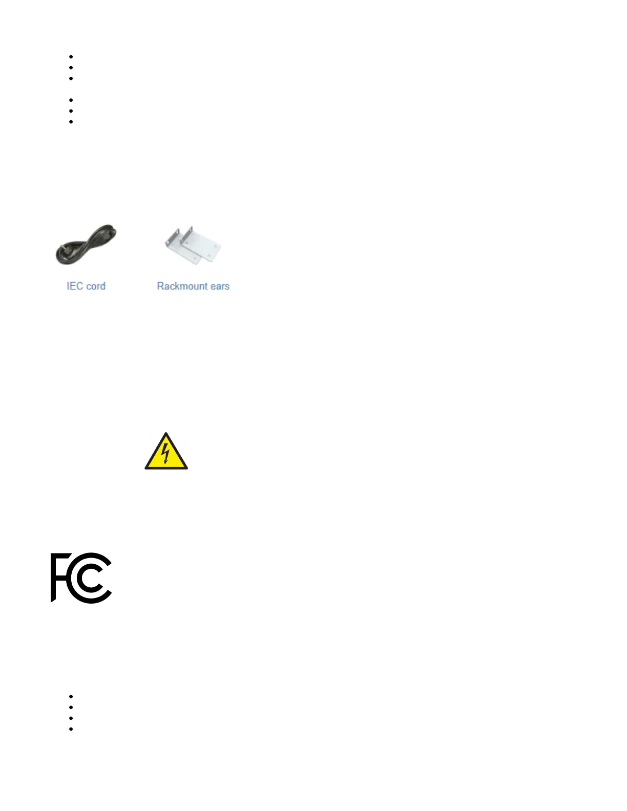
Accessories
Package includes the following accessories that come with the device:
Please visit wiki pages for MikroTik SFP module compatibility table: https://wiki.mikrotik.com/wiki/MikroTik_SFP_module_compatibility_table
Operating system support
The device supports dual boot SwOS software version 2.9 and RouterOS v6. The specific factory-installed version number is indicated in the RouterOS
menu /system resource. Other operating systems have not been tested.
https://wiki.mikrotik.com/wiki/SwOS
Safety Notice
Electric shock hazard. This equipment is to be serviced by trained personnel only.
Federal Communication Commission Interference Statement
This equipment has been tested and found to comply with the limits for a Class B digital device, pursuant to Part 15 of the FCC Rules. These limits are
designed to provide reasonable protection against harmful interference in a residential installation.
This equipment generates, uses and can radiate radio frequency energy and, if not installed and used in accordance with the instructions, may cause
harmful interference to radio communications. However, there is no guarantee that interference will not occur in a particular installation. If this equipment
does cause harmful interference to radio or television reception, which can be determined by turning the equipment off and on, the user is encouraged to
try to correct the interference by one of the following measures:
Reorient or relocate the receiving antenna.
Increase the separation between the equipment and receiver.
Connect the equipment into an outlet on a circuit different from that to which the receiver is connected.
Consult the dealer or an experienced radio/TV technician for help.
 Loading...