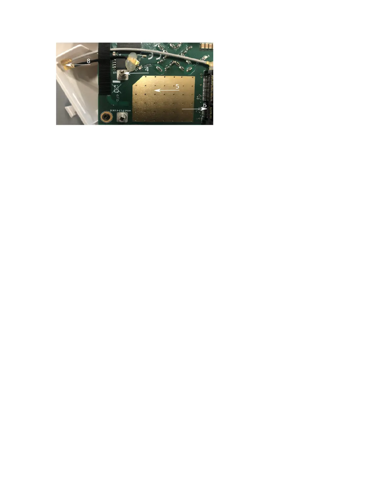
4.
5.
6.
7.
8.
9.
10.
1.
2.
3.
Locate the miniPCIe slot on the PCB and remove two factory attached screws;
Attach provided a thick thermal pad to the card, and install the card into miniPCIe slot so that the thermal pad is between PCB and card;
Insert your desired card;
The secure card is in place using previously removed two screws;
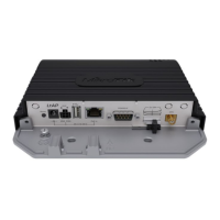
Attach the grey uFL connector to the MAIN antenna connector of the modem, attach the black cable to the secondary (or AUX) connector;
Attach a thinner thermal pad to the top of the card;
Reassemble.
After reassembly, slide in the SIM card from your mobile operator into the SIM slot, with the chips facing up as shown on the port label. The slot accepts
MicroSIM (3FF).
Powering
The device can be powered from 12-57 V 802.3af/at sources and also Passive PoE injectors (one power supply and PoE injector are included).
Maximum power consumption 6 W.
Connecting to a PoE Adapter:
Connect the Ethernet cable from the device to the PoE+DATA port of the PoE adapter;
Connect an Ethernet cable from your local network (LAN) to the PoE adapter;
Connect the power cord to the adapter, and then plug the power cord into a power outlet.
Mounting

 Loading...