MIMAKI ENGINEERING CO., LTD.
5. Checking damage of the print heads
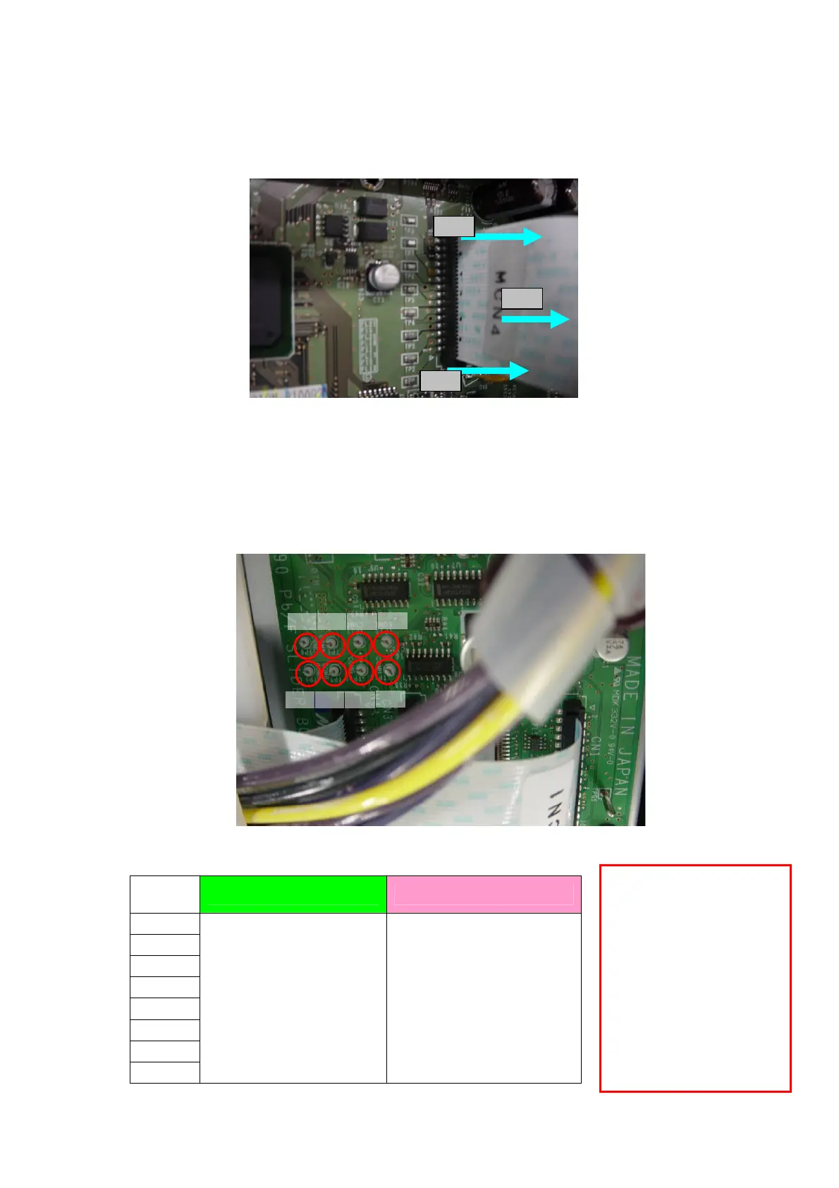
(1) Release the lock for HDC_FFC 130/160 ASSY connected to CN1-CN4 in the Main PCB ASSY.
(2) Remove HDC_FFC 130/160 ASSY.
1
(2)
1
(3) Measure resistant between the test pin TP6-13 and GND in the Ink slider PCB and judge whether
the value is good or not with List 2
Connect the Negative terminal of the tester to the GND test pin (TPG1-5) and measure the
resistance by getting the Positive terminal touch to TP6-13
List 2
TP8
TP13
TP12TP7 TP9
TP10
TP11TP6
Notes:
If any of COM line defect
is found, the print head is
broken. Please replace the
print heads first.
If connecting normal Main
PCB without replacing
them, it will cause the PCB
damage continuously.
Test pin
Normal print head Abnormal print head
TP6
TP7
TP8
TP9
TP10
TP11
TP12
TP13
10MΩ and more
Good
Less than 10MΩ
Bad
3/7 D900674 Ver1.1
 Loading...


