11
en
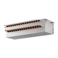
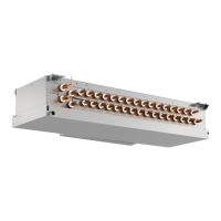
3. Installing the hydro unit
3.1. Checking the accessories with the hydro
unit
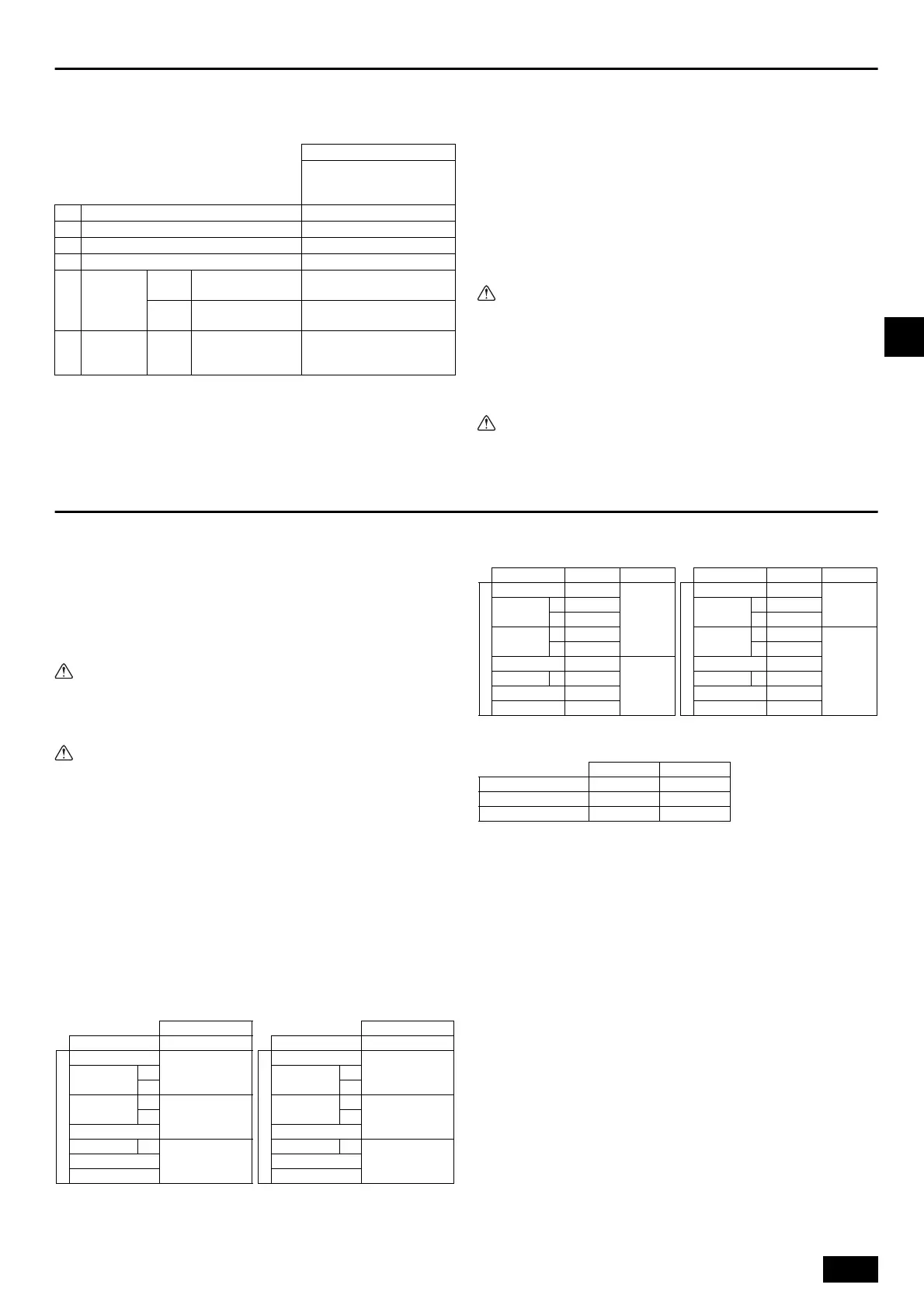
The following items are supplied with each hydro unit.
3.2. Installing hydro units
Bases
• Be sure to install unit in a place strong enough to withstand its weight. If the base
is unstable, reinforce with a concrete base.
• The unit must be anchored on a level surface. Use a level to check after installation.
• If the unit is installed near a room where noise is a problem, using an anti-
vibration stand on the base of the unit is recommended.
[Fig. 3.2.1] (P.3)
• Be sure to install unit in a place strong enough to withstand its weight.
Any lack of strength may cause unit to fall down, resulting in a personal injury.
• Have installation work in order to protect against earthquake.
Any installation deficiency may cause unit to fall down, resulting in a
personal injury.
Be sure to install the hydro unit horizontally. Check using a level. If the
unit is installed at an angle, drain water may leak out.
• Be sure to install the unit horizontally.
Install the hydro unit level (less than 1° tilt), so that the drain pan (option)
can function correctly.
4. Connecting refrigerant pipes and drain pipes
4.1. Connecting refrigerant pipes
1. Be sure to use non-oxidative brazing where necessary. If you do not use non-
oxidative brazing, it may clog the pipes.
When brazing the outdoor unit connecting port of hydro unit, supply nitrogen gas
into the pipe between the outdoor unit and hydro unit.
2. After completing pipe connection, support the pipes to ensure that load is not
imparted to the hydro unit’s end connections.
3. When using mechanical couplings, use the ones that meet ISO14903.
When installing and moving the unit, do not charge it with refrigerant other
than the refrigerant (R32) specified on the unit.
- Mixing of a different refrigerant, air, etc. may cause the refrigerant cycle to
malfunction and result in severe damage.
• Use refrigerant piping made of phosphorus deoxidized copper and copper
alloy seamless pipes and tubes. In addition, be sure that the inner and outer
surfaces of the pipes are clean and free of hazardous sulphur, oxides, dust/
dirt, swarf, oils, moisture, or any other contaminants.
- R32 is high-pressure refrigerant and can cause the existing piping to burst.
• Store the piping to be used during installation hydro unit and keep both
ends of the piping sealed until just before brazing. (Store elbows and other
joints in a plastic bag.)
- If dust, dirt, or water enters the refrigerant cycle, deterioration of the oil and
compressor failure may result.
- Infiltration of a large amount of mineral oil may cause the refrigerant oil to
deteriorate.
• Do not vent R32 into the atmosphere.
1. Size of hydro unit’s end connection piping
[Fig. 4.1.1] (P.3)
Note:
• Be sure to use non-oxidative brazing.
<Refrigerant piping connection examples>
• Obtain joints and elbows on site as necessary according to the pipe diameter,
and connect the pipes as shown in the figures below.
[Fig. 4.1.2] (P.4)
(1) When routing the pipes through the front of the unit
(2) When routing the pipes through the bottom of the unit
(3) Pipe connection port and connecting pipe
Model name
CMH-WM250V-A
CMH-WM350V-A
CMH-WM500V-A
Item Qty
1 Installation manual 1
2 Air vent manual 1
3 Auto air vent valve (3/4 parallel thread) 1
4
Strainer
(20 mesh)
W250
W350
32A screw-in
housing (40A)
1
W500
40A screw-in
housing (50A)
1
5
Refrigerant
connection
pipe
W350
W500
ø25.4 –ø28.58
(ø1 – ø1-1/8)
1
A M10 anchor bolt (not supplied)
B (Incorrect installation) The corner section is not securely received.
C Fixing bracket for post-installed anchor bolts (not supplied) (To be fixed with three screws)
D Anti-vibration rubber pad (The pad needs to be large enough to cover the entire width of
each unit leg.)
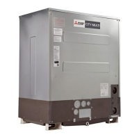
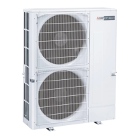
1. Hydro units connectable to outdoor units
Standard models High-efficient models
Hydro unit
Unit model Model name
Outdoor unit side
PUHY-M200
CMH-
WM250V-A
PUHY-M250
*1
*2
PUHY-M300
*3
CMH-
WM350V-A
*4
PUHY-M350
PUHY-M400 *5
CMH-
WM500V-A
PUHY-M450
PUHY-M500
Hydro unit
Unit model Model name
Outdoor unit side
PUHY-EM200
CMH-
WM250V-A
PUHY-EM250
*1
*2
PUHY-EM300
*3
CMH-
WM350V-A
*4
PUHY-EM350
PUHY-EM400 *5
CMH-
WM500V-A
PUHY-EM450
PUHY-EM500
*1 When the piping length from the outdoor unit to the hydro unit is less than 90 m (295 ft)
*2 When the piping length from the outdoor unit to the hydro unit is 90 m (295 ft) or more
*3 When the piping length from the outdoor unit to the hydro unit is less than 40 m (131 ft)
*4 When the piping length from the outdoor unit to the hydro unit is 40 m (131 ft) or more
*5 When the unit is used alone
A To outdoor unit
B End connection (brazing)
C Hydro unit
D To ma in pipin g
E Indoor unit
<A> Liquid side A Refrigerant piping
<B> Gas side B Elbow
C On-site piping
2. Connecting pipe diameter of outdoor unit
Standard models High-efficient models
Unit model Liquid Gas
Outdoor unit side
PUHY-M200
ø9.52 (ø3/8)
ø22.2
(ø7/8)
PUHY-M250
*1
ø9.52 (ø3/8)
*2
ø12.7 (ø1/2)
PUHY-M300
*3
ø9.52 (ø3/8)
*4
ø12.7 (ø1/2)
PUHY-M350
ø12.7 (ø1/2)
ø28.58
(ø1-1/8)
PUHY-M400
*5
ø12.7 (ø1/2)
PUHY-M450
ø15.88 (ø5/8)
PUHY-M500
ø15.88 (ø5/8)
Unit model Liquid Gas
Outdoor unit side
PUHY-EM200
ø9.52 (ø3/8)
ø22.2
(ø7/8)
PUHY-EM250
*1
ø9.52 (ø3/8)
*2
ø12.7 (ø1/2)
PUHY-EM300
*3
ø9.52 (ø3/8)
ø28.58
(ø1-1/8)
*4
ø12.7 (ø1/2)
PUHY-EM350
ø12.7 (ø1/2)
PUHY-EM400
*5
ø12.7 (ø1/2)
PUHY-EM450
ø15.88 (ø5/8)
PUHY-EM500
ø15.88 (ø5/8)
3. Connecting pipe diameter of hydro unit
If the connecting pipe diameter of hydro unit differs from that of outdoor unit, expand
or reduce the pipe diameter at the inlet of the hydro unit.
Liquid Gas
CMH-WM250V-A ø9.52 (ø3/8) ø22.2 (ø7/8)
CMH-WM350V-A ø12.7 (ø1/2) ø25.4 (ø1)
CMH-WM500V-A ø15.88 (ø5/8) ø25.4 (ø1)
WT09052X01_en.book 11 ページ 2019年1月17日 木曜日 午前10時49分
 Loading...