1919
(Drainage)
When drain socket
is installed
2
246
When drain socket
is installed
233
When electrical box
is pulled down
Electrical box
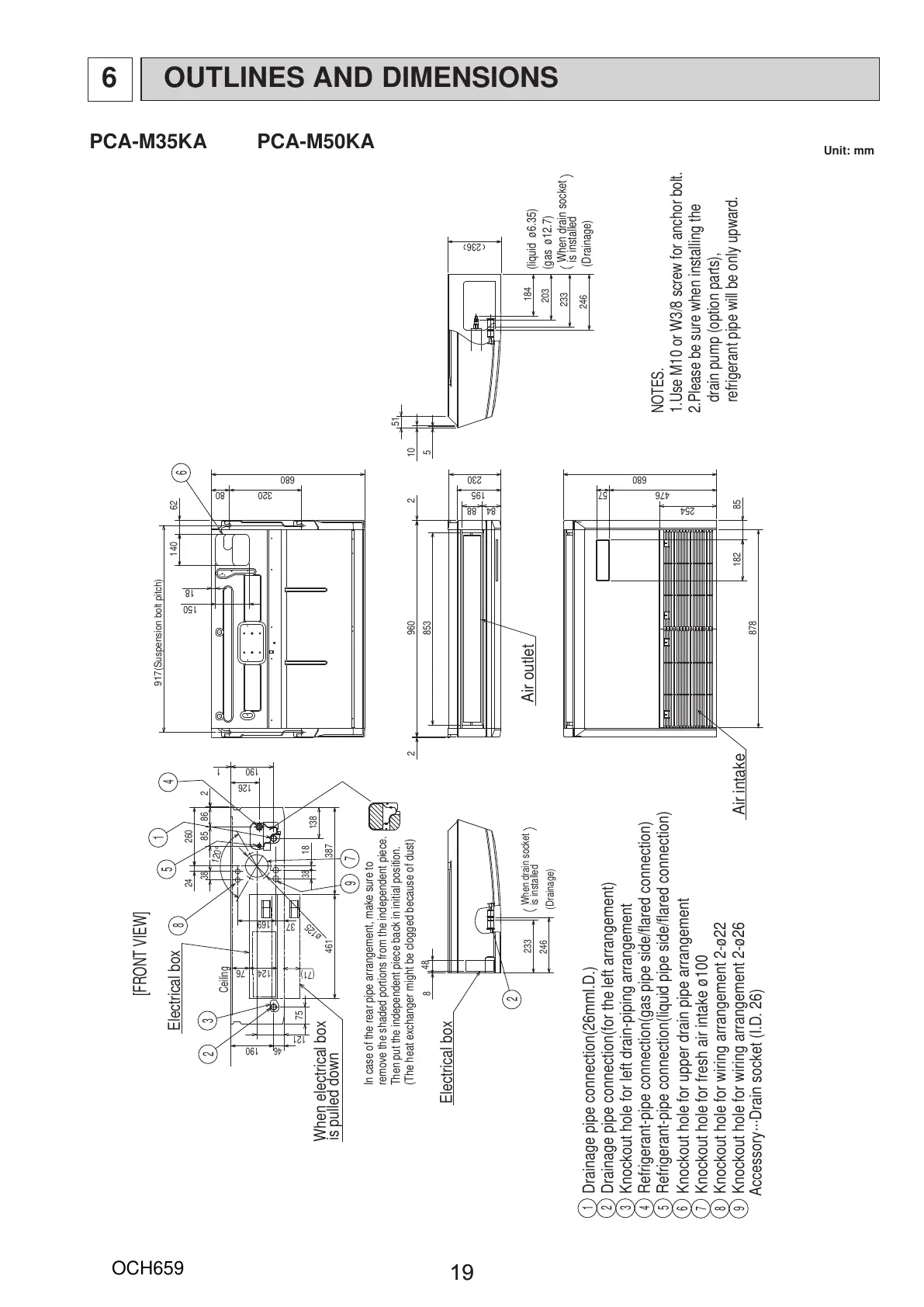
NOTES.
1.Use M10 or W3/8 screw for anchor bolt.
2.Please be sure when installing the
drain pump (option parts),
refrigerant pipe will be only upward.
Electrical box
233
Air outlet
Air intake
9
6
7
8
5
1
2
3
4
Knockout hole for upper drain pipe arrangement
Knockout hole for fresh air intake ø100
Knockout hole for wiring arrangement 2-ø22
Knockout hole for wiring arrangement 2-ø26
Drainage pipe connection(26mmI.D.)
Drainage pipe connection(for the left arrangement)
Knockout hole for left drain-piping arrangement
Refrigerant-pipe connection(gas pipe side/flared connection)
Refrigerant-pipe connection(liquid pipe side/flared connection)
1
In case of the rear pipe arrangement, make sure to
remove the shaded portions from the independent piece.
Then put the independent piece back in initial position.
(The heat exchanger might be clogged because of dust)
5
10
51
246
(Drainage)
(gas ø12.7)
(liquid ø6.35)
150
62140
18
917(Suspension bolt pitch)
320
680
80
84 88
195
230
57
254
476
680
182 85
878
8
48
26024
38
85 86 2
126
169
121
190
18
38
120°
960 22
853
124 76
46
190
75
387461
3
8
Ceiling
5
1
4
7
184
203
ø125
6
9
37
138
2
[FRONT VIEW]
Accessory···Drain socket (I.D. 26)
(71)
236
PCA-M35KA PCA-M50KA
Unit: mm
OUTLINES AND DIMENSIONS6
 Loading...