12 13
TCH122
7
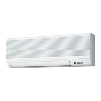
REFRIGERANT SYSTEM DIAGRAM
Heat exchanger
Room temperature
detection thermistor TH21
Pipe temperature detection
thermistor/ inlet
TH22
Water inlet
connection
Manual air purge valve
Water inlet
Water outlet
7/8 (22)
7/8 (22)
Item
Model
Pipe temperature detection
thermistor/ outlet
TH23
Water outlet
connection
PKFY-WL04/06/08/12/15NLMU-E
Unit: in (mm)
PKFY-WL04NLMU-E.TH PKFY-WL06NLMU-E.TH PKFY-WL08NLMU-E.TH
PKFY-WL12NLMU-E.TH PKFY-WL15NLMU-E.TH
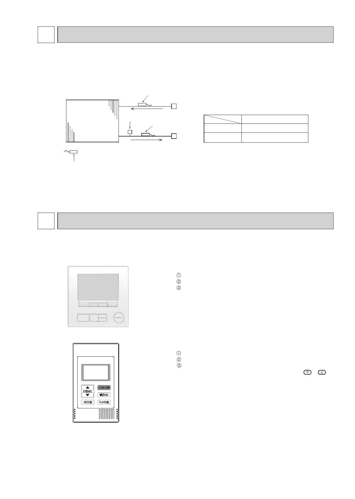
MICROPROCESSOR CONTROL
8
<How to operate>
Press POWER ON/OFF button.
Press the operation MODE button to display COOL.
Press the TEMP. button to set the set temperature.
NOTE: The set temperature changes 1°F when the or
button is pressed one time. Cooling 67 to 87°F
<How to operate>
Press ON/OFF button.
Press [F1] button to display COOL.
Press [F2] [F3] button to set the set temperature.
NOTE: The settable temperature range varies with the model of
outdoor units and remote controller.
INDOOR UNIT CONTROL
8-1. COOL OPERATION
MENU
ON
OFF
RETURN
SELECT
HOLD
.
 Loading...