31
30
TCH122
PHOTOS/FIGURES OPERATION PROCEDURE
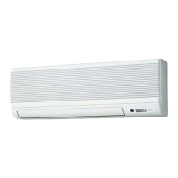
8. REMOVING THE HEAT EXCHANGER
(1)
Remove the panel and the corner box (Refer to procedure 1).
(2) Remove the electrical box (Refer to
procedure
3) and the
nozzle assembly (Refer to
procedure
4).
(3) Remove the water cover.
(4) Remove the pipe thermistors. (Refer to procedure 7).
(5) Disconnect the connector (CN60) on the indoor controller
board.
(6) Remove the motor bed together with fan motor and motor
band (Refer to procedure 6).
(7) Remove 2 screws fixing the left side of the heat exchanger.
(See Photo 10)
(8) Remove the heat exchanger.
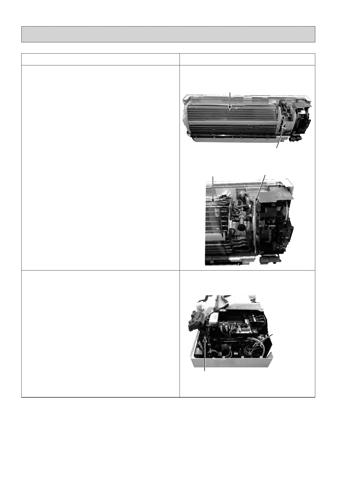
9. REMOVING THE ROOM TEMPERATURE THERMISTOR
(1) Remove the panel and corner box. (Refer to
procedure
1)
(2) Remove the electrical box covers. (Refer to
procedure
2)
(3) Remove the room temperature thermistor.
(4) Disconnect the connector (CN20) on the indoor controller
board.
Photo 12
Photo 13
Indoor controller
board
Room temp. thermistor
(TH21)
Photo 14
Heat exchanger
Water cover
Connect for ground
Heat exchanger
 Loading...