-
312
-
'12 • PAC-T-173
(8) Indoor fan motor protection
When the air conditioner is operating and the indoor fan motor is turned ON, if the indoor fan motor has operated at 300 rpm or
underformorethan30seconds,theunitentersrstinthestopmodeandthenstopstheentiresystem.
(9) Serial signal transmission error protection
(a)
Purpose:
Prevents malfunction resulting from error on the indoor
↔
outdoor signals.
(b)
Detail of operation:
If the compressor is operating and a serial signal cannot be received from the indoor control with outdoor
control having serial signals continues for 7 minute and 35 seconds, the compressor is stopped. After the
compressor has been stopped, it will be restarted after the compressor start delay if a serial signal can
be received again from the indoor control.
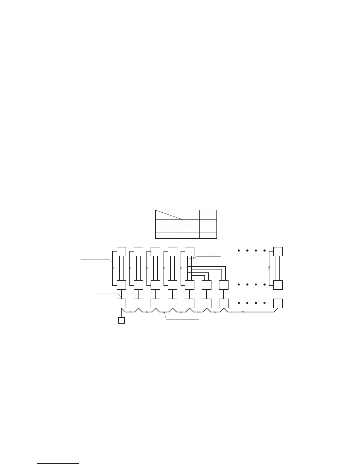
(10) Plural unit control – Control of 16 units group by one remote controller
(a) Function
One remote controller switch can control a group of multiple number of unit (Max. 16 indoor units). “Operation mode”
which is set by the remote controller switch can operate or stop all units in the group one after another in the order of unit
No.
(1)
. Thermostat and protective function of each unit function independently.
Note (1) Unit No. is set by SW1 on the interface PCB. Unit No. setting by SW1 is necessary for the interface only. In cases of the twin and triple
specication,itisnecessarysetforthemasterandtheslaveunits.ThiscanbeselectedbySW3.(Allaresetforthemasterunitattheshipping
from factory.)
SW1: For setting of 0 – 9, A – F
SW3: For setting of master and slave units
(See table shown at right.)
(2) UnitNo.maybesetatrandomunlessduplicated,itshouldbebettertosetorderlylike0,1,2…,Ftoavoidmistake.
(b) Display to the remote controller
1) Center or each remote controller basis, heating preparation: the youngest unit No. among the operating units in the
remote mode (or the center mode unless the remote mode is available) is displayed.
2) Inspection display: Any of unit that starts initially is displayed.
3) Conrmationofconnectedunits
Pressing “AIR CON No.” button on the remote controller displays the indoor unit address. If “
▲
” “
▼
” button is
pressed at the next, it is displayed orderly starting from the unit of youngest No.
 Loading...