HEAD OFFICE : MITSUBISHI DENKI BLDG MARUNOUTI TOKYO 100-8310 TELEX : J24532 CABLE MELCO TOKYO
HIMEJI WORKS : 840, CHIYODA CHO, HIMEJI, JAPAN
4. Terminal Layouts
The following selection of terminal layouts are taken from the FX
1N
product range.
Note: All layouts are diagrammatic and are only intended to aid the creation of wiring diagrams.
4.1 AC Powered Main Units
COM X1
X0 X4
X5
COM Y0 Y1 Y2 Y3
X3
X2
24+
X7
X6
Y5
X12
X13X11
X10
X15
X14
Y6 Y10
Y7 Y11COM0 COM1 COM2 COM3 Y4 COM4
FX
1N
-24MR / 24MT
N
L
COM X1
N X0 X4
FX1N-60MR / 60MT
X5
COM
Y0 Y1 Y2
Y3
X3
X2
24+
COM0 COM1 COM3COM2
L
X7
X6
Y5
COM4
X12
X13X11
X10
X15
X14
Y6Y4 Y14
Y7 Y11
X20
X21X17
X16
X23
X22 X24
X25
X26
X27
Y10 Y12
Y13
COM5
Y16
Y15 Y17
X31
X30 X32
X33
X34
X35
X40
X41
X42
X43
Y20 Y22
Y21 Y23
COM6
Y24 Y26
Y25 Y27
COM7
X36
X37
COM
X1
N X0 X4
FX
1N
-40MR / 40MT
X5
COM
Y0 Y1 Y2
Y3
X3
X2
24+
COM0 COM1 COM3COM2
L
X7
X6
Y5
COM4
X12
X13X11
X10
X15
X14
Y6Y4 Y14
Y7 Y11
X20
X21X17
X16
X23
X22 X24
X25
X26
X27
Y10 Y12
Y13
COM5
Y16
Y15 Y17
4.2 DC Powered Main Units
COM X1
X0 X4
FX
1N
-24MR-D / 24MT-D
X5
COM Y0 Y1 Y2 Y3
X3
X2
24+
COM0 COM1 COM3COM2
X7
X6
Y5
COM4
X12
X13X11
X10
X15
X14
Y6
Y4
Y10
Y7 Y11
-
+
COM X1
X0 X4
FX
1N
-40MR-D / MT-D
X5
COM Y0 Y1 Y2
Y3
X3
X2
24+
COM0 COM1 COM3COM2
X7
X6
Y5
COM4
X12
X13X11
X10
X15
X14
Y6Y4 Y14
Y7 Y11
X20
X21X17
X16
X23
X22 X24
X25
X26
X27
Y10 Y12
Y13
COM5
Y16
Y15 Y17
-
+
COM
X1
X0 X4
FX
1N
-60MR-D / MT-D
X5
COM
Y0 Y1 Y2
Y3
X3
X2
24+
COM0 COM1 COM3COM2
X7
X6
Y5
COM4
X12
X13X11
X10
X15
X14
Y6Y4 Y14
Y7 Y11
X20
X21X17
X16
X23
X22 X24
X25
X26
X27
Y10 Y12
Y13
COM5
Y16
Y15 Y17
X31
X30 X32
X33
X34
X35
X40
X41
X42
X43
Y20 Y22
Y21 Y23
COM6
Y24 Y26
Y25 Y27
COM7
X36
X37
-
+
5. Example Wiring
If during the wiring of these products or associated products concern is felt, please contact a professional
electrician who is trained in the local and national standards applicable to the installation site.
Wiring cautions
• Do not run input signals in the same multicore cable as output signals or allow them to
share the same wire.
• Do not lay I/O signal cables next to power cables or allow them to share the same trunking
duct. Low voltage cables should be reliably separated or insulated with regard to high
voltage cabling.
• Where I/O signal lines are used over an extended distance consideration for voltage drop
and noise interference should be made.
• Always ensure that mounted units and blocks are kept as far as possible from
high-voltage cables, high-voltage equipment and power equipment.
Both Japanese and World Specification Extension blocks/units and special function blocks can be used
with these main units.
5.1 AC Power Supply
"
Power supply 100-240V AC +10% -15% 50-60Hz
#
Emergency stop
$
Power supply switch
%
Power ON pilot indicator
&
Power supply for loads
'
Ground
(
Fuse
)
Main unit
*
Breaker
AC/DC
Converter
Extension block
Extension unit
MC
PL
MC
MC MC
24+
24+
COM
24+
COM
L
N
L
N
#
$
%
"
&
&
'
(
)
*
5.2 DC Power Supply
"
Power supply 12-24V DC +20% -15%
20.4-28.8V DC when using extension unit.
#
Circuit protector or fuse
$
Emergency stop
%
Power supply switch
&
Power ON pilot indicator
'
Power supply for loads
(
Ground
)
Fuse
*
Main unit
+
Breaker
DC/DC
Converter
Extension block
Extension unit
MC
PL
MC
MC MC
24+
24+
COM
COM
-
+
L
N
X000
X001
"
#
#
$
%
&
''
(
)
*
+
#
+
-
+
-
5.3 Input
Note
• When using a DC powered unit, the input circuit power supply should be used. If an
external 24V DC supply is used, the FX
1N
will not operate correctly.
• Japanese specification models are ALWAYS SINK input
"
AC Model - Service supply
DC Model - Input circuit power supply
#
NPN Sensor
$
Input Device Contact
%
Main unit
24+ COM
COM
X0 X1 X2
NPN
"
#
$
%
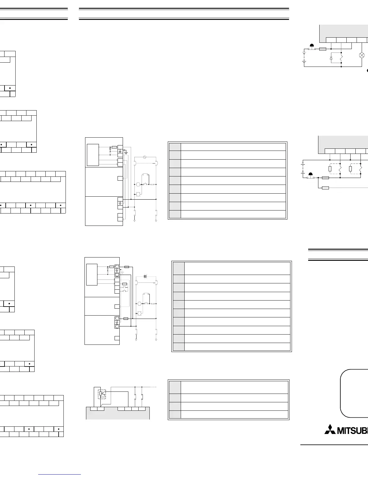
5.4 Output
Typical Relay
"
Do not use this terminal
#
Fuse
$
Surge absorbing Diode
%
External Mechanical Interlock
&
Emergency Stop
'
Noise Suppressor 0.1
µ
F
capacitor + 100-200
Ω
resistor
Contactor
(
Valve
)
Incandescent Lamp
*
DC Power Supply
+
AC Power Supply
COM0
Y0 Y1 Y2 Y3
COM1 COM2
Y4 Y5
MC1 MC2
MC2 MC1
+
"
#
$
%
&
&
(
)
*
+
Japanese model Transistor
"
Do not use this terminal
#
Emergency Stop
$
Fuse
%
External Mechanical Interlock
&
DC Power Supply
COM0
Y0 Y1 Y2 Y3
COM1 COM2
Y4 Y5
MC1 MC2
MC2 MC1
+
"
#
$
$
%
&
Additional information
Additional information regarding:
• Product Outline
• World Specification Extension Units / Blocks and Special Function Blocks
• Configuration Schematics
• Current Consumption and Rules of Expansion
• Back up Data procedure and details
• Diagnostic information, Instruction and Device lists
Can be found in the FX
1N
HANDY MANUAL (JY992D87501 JAPANESE ONLY). It is strongly
recommended that this manual is read and understood before the use or configuration of this
product.
Manual number : JY997D07901
Manual revision: A
Date : November 2002
JY997D07901A
Effective November 2002
Specifications are subject to
change without notice

 Loading...


