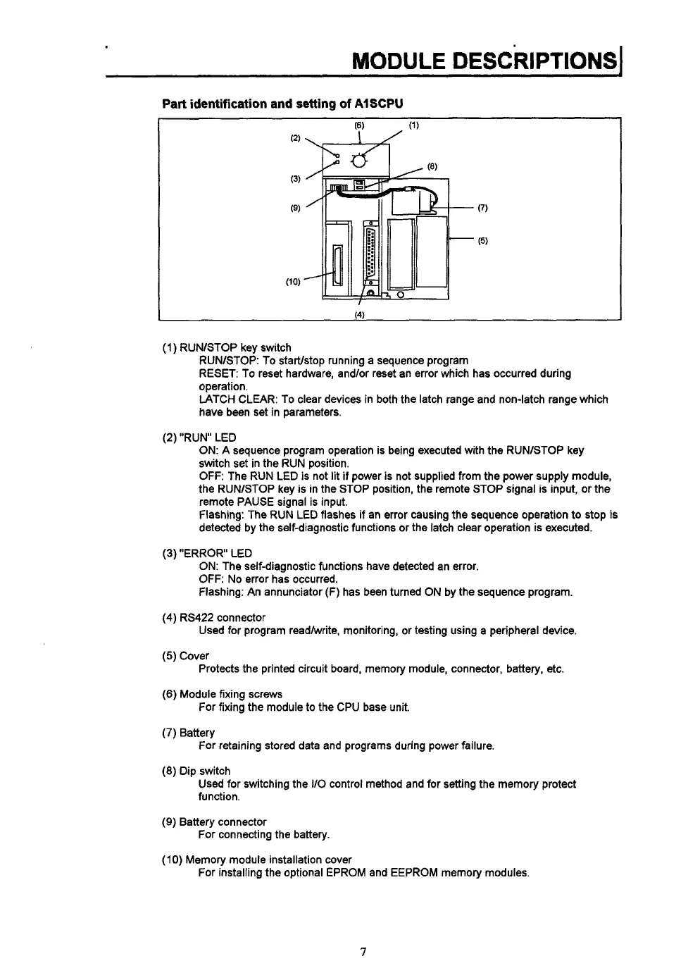
Part identification and setting
of
AISCPU
I
(1)
RUNlSTOP key switch
RUNASTOP: To startlstop running a sequence program
RESET: To reset hardware, and/or reset an error which has occurred during
operation.
LATCH CLEAR: To clear devices in both the latch range and non-latch range which
have been set in parameters.
(2) "RUN LED
ON:
A sequence program operation is being executed with the RUNlSTOP key
switch set in the RUN position.
OFF:
The RUN LED is not lit
if
power
is
not supplied from the power supply module,
the RUNlSTOP key
is
in the STOP position, the remote STOP signal is input, or the
remote PAUSE signal is input.
flashing: The RUN LED flashes if an error causing the sequence operation to stop is
detected by the self-diagnostic functions or the latch clear operation is executed.
(3)
"ERROR LED
ON: The self-diagnostic functions have detected an error.
OFF:
No error has occurred.
Flashing: An annunciator
(F)
has been turned ON by the sequence program.
Used for program readhvrite, monitoring, or testing using a peripheral device.
(4)
RS422 connector
(5)
Cover
(6)
Module fixing screws
(7)
Battery
(8)
Dip switch
Protects the printed circuit board, memory module, connector, battery, etc.
For fixing the module to the CPU base unit.
For retaining stored data and programs during power failure.
Used for switching the
IlO
control method and for setting the memory protect
function.
(9)
Battery connector
For connecting the battery.
(IO)
Memory module installation cover
For installing the optional EPROM and EEPROM memory modules.
7
 Loading...