11
11
1. Indoor unit
11
11
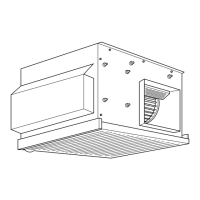
1-1. Accessory
The unit is provided with the following accessory:
11
11
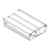
1-2. Selecting an installation site
• Select a site with sturdy fixed surface sufficiently durable against the weight of
unit.
• Before installing unit, the routing to carry in unit to the installation site should
be determined.
• Select a site where the unit is not affected by entering air.
• Select a site where the flow of supply and return air is not blocked.
• Select a site where refrigerant piping can easily be led to the outside.
• Select a site which allows the supply air to be distributed fully in room.
• Do not install unit at a site with oil splashing or steam is produced much quan-
tity.
• Do not install unit at a site where combustible gas may generate, flow in, stag-
nate or leak.
• Do not install unit at a site where equipment generating high frequency waves
(a high frequency wave welder for example) is provided.
• Do not install unit at a site where fire detecter is located at the supply air side.
(Fire detector may operate erroneously due to the heated air supplied during
heating operation.)
• When special chemical product may scatter around such as site chemical plants
and hospitals, full investigation is required before installing unit. (The plastic
components may be damaged depending on the chemical product applied.)
11
11
1-2.1. Install the indoor unit on a ceiling strong
enough to sustain its weight
Warning:
The unit must be securely installed on a structure that can sustain its weight.
If the unit is mounted on an unstable structure, it may fall down causing
injuries.
11
11
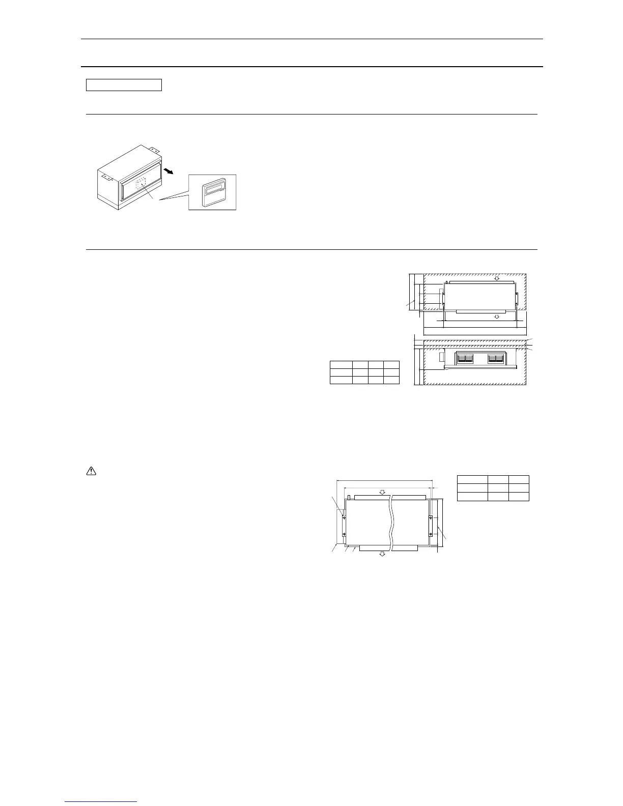
1-2.2. Securing installation and service space
• Select the optimum direction of supply airflow according to the configuration of
the room and the installation position.
• As the piping and wiring are connected at the bottom and side surfaces, and
the maintenance is made at the same surfaces, allow a sufficient space. For
the efficient suspension work and safety, provide as much space as possible.
Service space
1 When connecting air inlet
2 When installing the suspension fixtures prior to installation of the in-
door unit without inlet duct and outlet duct
3 When hanging the indoor unit directly without inlet duct and outlet duct
A Service space B Suspension bolt pitch
C Air inlet D Air outlet
[Fig.
11
11
1-2.2.1]
XY Z
PEH-7,8 1240 1280 1880
PEH-10 1440 1480 2080
 Loading...