EasyManua.ls Logo

Mitsubishi SCM45ZD-S User Manual

Mitsubishi SCM45ZD-S
40 pages
To Next Page IconTo Next Page
To Previous Page IconTo Previous Page
Page #34 background image
-
31
-
LO
MID
HI
AUTO
HI POWER
ECONO
ON OFF
AM PM
HI POWER
TEMP
ECONO
AIR FLOW
CANCEL
ON OFF
RESERVE
TIMER
TIME
ACL
FAN SPEED
ON
MODE
LO
MID
HI
AUTO
TIME
OFF
HI POWER
ECONO
ON OFF
AM PM
FAN SPEED button
Each time the button is pushed, the indi-
cator is switched over in turn.
The above illustration shows all controls, but in practice
only the relevant parts are shown.
OPERATION MODE select button
Each time the button is pushed, the indi-
cator is switched over in turn.
AIR FLOW button
This button changes the flap mode. When
pressed, this button changes the mode in the
following order:
ON/OFF button
Press for starting operation, press again for
stopping.
HI POWER button
This button changes the HI POWER mode.
ECONOMY button
This button changes the ECONOMY mode.
RESET switch
Switch for resetting microcomputer.
ON TIMER button
This button selects ON TIMER operation.
Clock switch
This switch for setting the clock.
OFF TIMER button
This button selects OFF TIMER operation.
TEMPERATURE button
This button sets the room temperature.
(This button changes the present time and
TIMER time.)
CANCEL button
This button cancels the ON timer and OFF
timer.
RESERVE button
This button sets the present time and
TIMER time.
S Indication section
OPERATION MODE Indicator
Indicates selected operation with lamp.
[
(Auto) • (Cool) • (Heat) • (Dry)]
TEMPERATURE Indicator
Indicates set temperature.
(Does not indicate temperature when operation
mode is on AUTO)
FAN SPEED Indicator
Indicates set air flow rate with lamp.
AIR FLOW Indicator
Shows selected flap mode.
HI POWER MODE indicator
Indicates during Hi power mode operation.
ECONOMY MODE indicator
Indicates during economy mode operation.
ON TIMER Indicator
Indicates during ON TIMER operation.
Clock Indicator
Indicates present time or timer setting time.
OFF TIMER Indicator
Indicates during OFF TIMER operation.
Models All models
Remote controller
S Operation section
(Air scroll) (SWING)
4 OUTLINE OF OPERATION CONTROL BY MICROCOMPUTER
4.1 Operation control function by remote control switch
This button is not used for SRRM-ZE series.
(Air flow direction adjustment can not be
performed.)
Question and Answer IconNeed help?

Do you have a question about the Mitsubishi SCM45ZD-S and is the answer not in the manual?

Mitsubishi SCM45ZD-S Specifications

General IconGeneral
BrandMitsubishi
ModelSCM45ZD-S
CategoryAir Conditioner
LanguageEnglish

Summary

1 GENERAL INFORMATION

Specific Features

Details on piping, connectable capacity, indoor unit types, inverter and fuzzy control.

How to Read Model Name

Explains the nomenclature used for model identification.

2 SELECTION DATA

2.1 Specifications

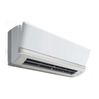
Presents detailed specifications for indoor unit models.

Outdoor Unit Specifications

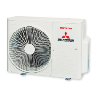
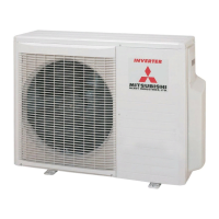
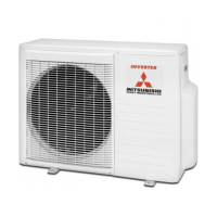
Presents detailed specifications for SCM45ZD-S, SCM60ZD-S, SCM80ZD-S outdoor units.

Operation Data

Provides cooling and heating capacity and power consumption data for unit combinations.

2.2 Range of Usage & Limitations

Details operating limits, restrictions, and maximum capacities for outdoor units.

2.3 Exterior Dimensions

Provides detailed exterior dimensions for indoor and outdoor units.

2.4 Piping System

Illustrates the refrigerant piping connections for the SCM45ZD-S unit.

2.5 Selection Chart

Provides charts for correcting capacity based on temperature and piping length.

3 ELECTRICAL DATA

Meaning of Marks

Defines symbols used in electrical diagrams for units.

4 OUTLINE OF OPERATION CONTROL

Operation Control by Microcomputer

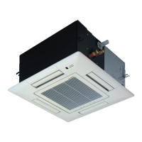
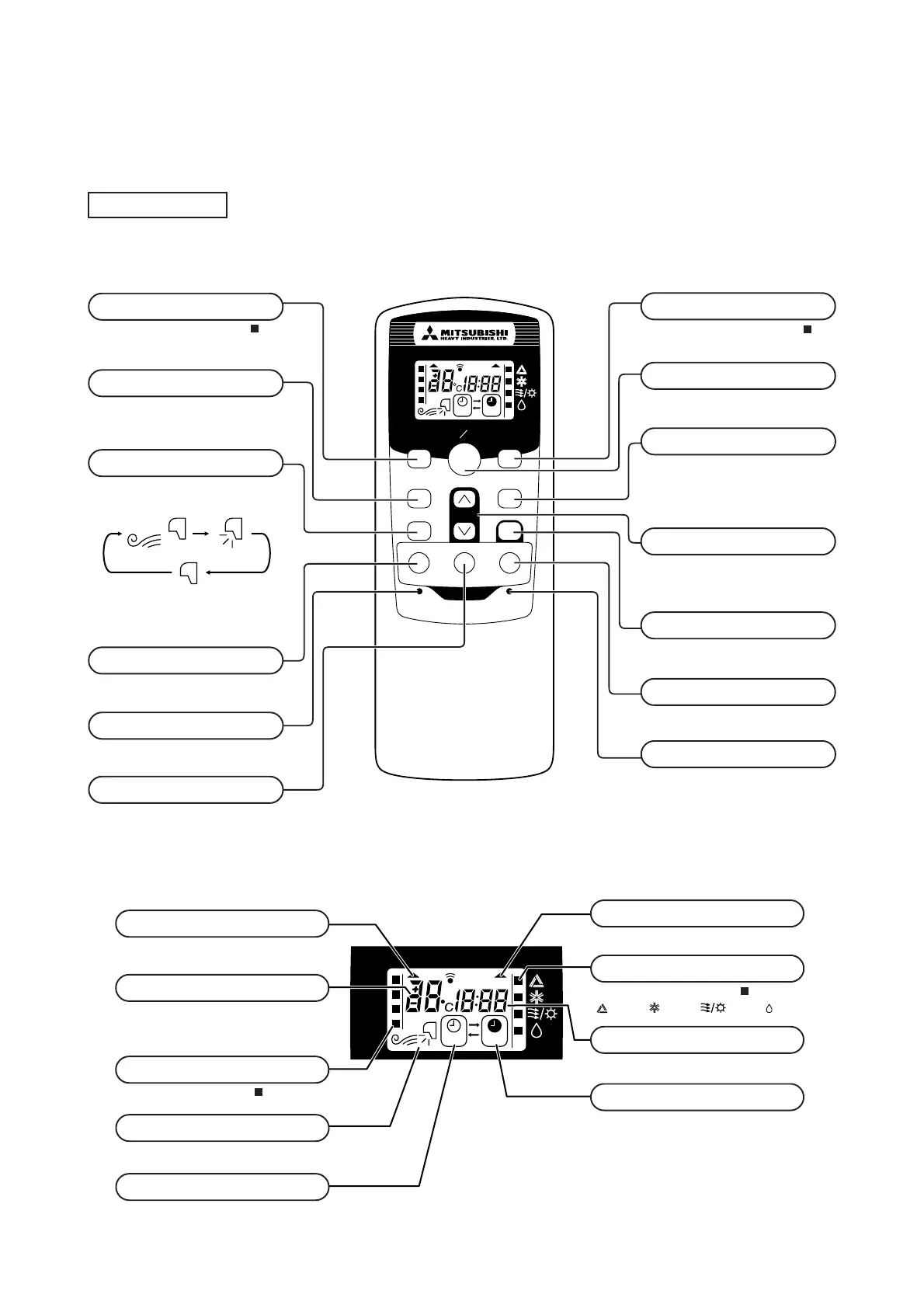
Explains operation functions controlled by the microcomputer via remote switch.

Unit Indication Section

Describes the function of indicator lights on indoor units.

5 INSTALLATION

Installation Tools

Lists special tools required for R410A refrigerant installation.

Refrigerant Piping Guidelines

Covers pipe selection, flare nut usage, and pipe connection procedures.

Pipe Connection Procedures

Details pipe working, tightening torque, and vacuuming for refrigerant piping.

PARTS LIST (Main parts)

Indoor Unit Parts

Lists main parts and part numbers for various indoor unit models.

Outdoor Unit Parts

Lists main parts and part numbers for various outdoor unit models.

Related product manuals