-
39
-
'11 • SCM-SM-110
1.7 External control (remote display) /control of input signal
(Refer to the FDTC, FDEN and FDUM series by 31 page)
(1) External control (remote display) output
Following output connectors (CNT) are provided on the printed circuit board of indoor unit.
Note (1) Please install the separately-sold Interface kit (SC-BIK-E). The output connector (CNT) is located on the circuit board of the Interface kit.
• Operation output:
Power to engage DC 12V relay (provided by the customer) is outputted during operation.
• Heating output:
Power to engage DC 12V relay (provided by the customer) is outputted during the heating operation.
• Compressor OPERATION output:
Power to engage DC 12V relay (provided by the customer) is outputted while the
compressor is operating.
• MALFUNCTION output:
When any error occurs, the power to engage DC 12V relay (provided by the customer) is outputted.
(2) Control of input signal
Control of input signal (switch input, timer input) connectors (CNT) are provided on the printed circuit board of
indoor unit.
However, when the operation of air conditioner is under the Center Mode, the remote control by CnT is invalid.
CnT Input
Unit
(CASE A)
Unit
(CASE B)
OFF
OFF
*ON
ON
ON
ON
OFF
OFF
OFF
ON
ON
ON
OFF
OFF
OFF
Note (1) The ON with the * mark indicates an
ON operation using the remote control
unit switch, etc.
*ON
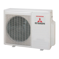
(a) Level input
If the factory settings (Jumper wire J1 EXTERNAL INPUT on the PCB of
indoor unit) are set, or “LEVEL INPUT” is se-
lected in the wired remote control’s indoor unit settings.
1) Input signal to CnT OFF
→
ON Air conditioner ON
2) Input signal to CnT ON
→
OFF Air conditioner OFF
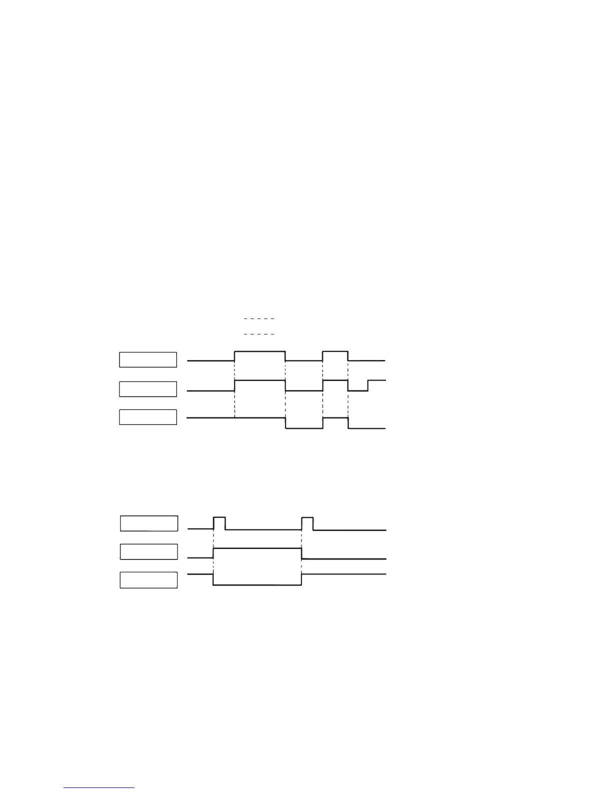
(b) Pulse input
When Jumper wire J1 on the PCB of
indoor unit is cut at the field or “PULSE INPUT” is selected in the wired remote con-
trol’s indoor unit settings.
Input signal to CnT becomes valid at OFF
→
ON only and the motion of air conditioner [ON/OFF] is inverted.
CnT Input
Unit
(CASE A)
Unit
(CASE B)
OFF
OFF
ON
ON
OFF
ON
OFF
ON
ON
OFF
OFF
 Loading...