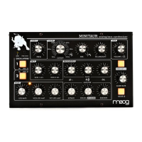
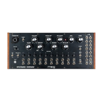
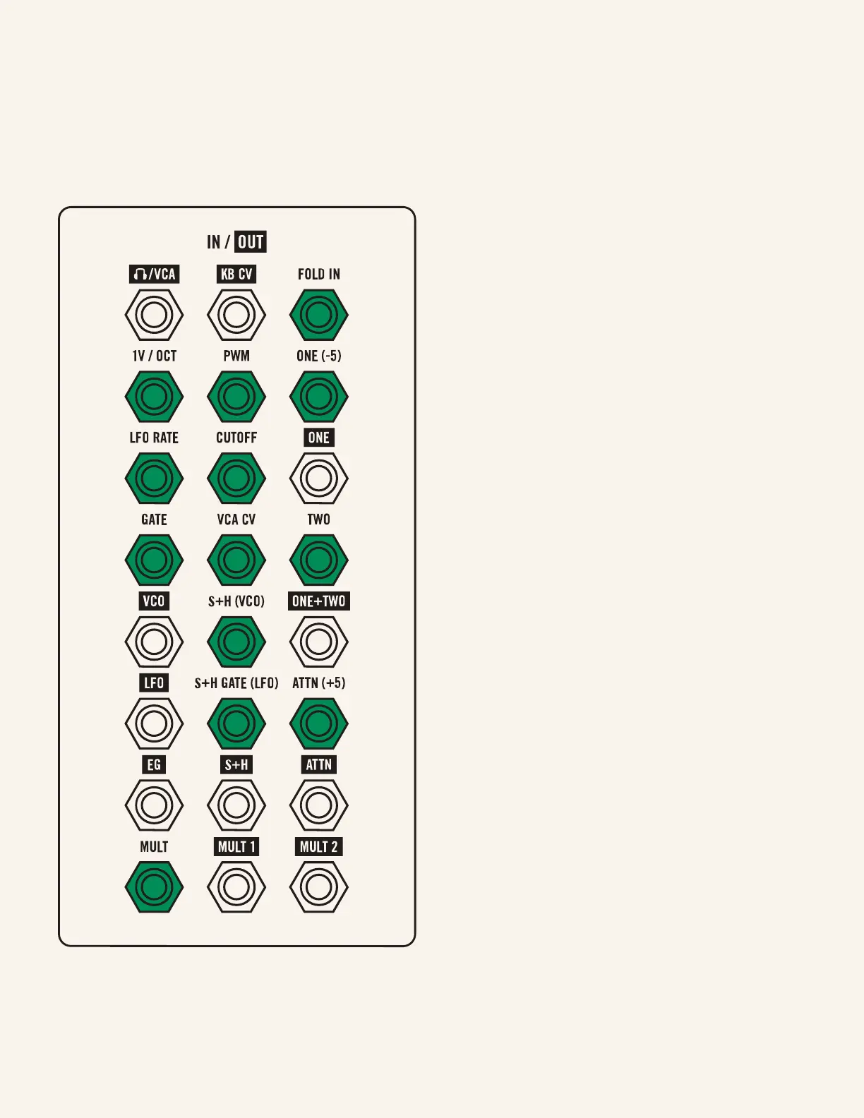
Inputs | 11
Inputs
FOLD IN (R1, C1)
Input to the wave folder. Plugging any signal
in here will patch it through the wave folder
(FOLD knob) and then directly to the filter.
Experiment with both the VCO and LFO
(at audio rate) patched here, and play with
their respective waveshapes and the FOLD
knob to explore the timbral possibilities of
wave folding.
1V/OCT (R2, C1)
Controls the frequency of the VCO. 1V/OCT
means this input is scaled such that every
volt will correspond to a doubling of the
frequency (i.e. a change of one octave). Patch
an LFO (through an attenuator) here for
vibrato or the S+H for random pitch changes.
PWM (R2, C2)
Controls the pulse width of the VCO’s pulse
wave. Patch the S+H here for random pulse
wave fluctuations.
ONE (-5) (R2, C3)
Input one for the mixer. The signal patched
here will be attenuated by the ONE LVL knob
and available at the ONE output and mixed
with TWO at the ONE+TWO output. Patch
any audio or control signals here and another
to TWO to add those signals together. You
can add the VCO + LFO for a two-oscillator
synth, the EG + LFO for wobbly envelopes,
or the S+H + EG for random note strengths!
The (-5) indicates that a negative five volt
oset is normalled to this input, allowing you
to shift the signal in TWO down five volts
with nothing patched to ONE.
Listed in order left to right by row;
R (Row) and C (Column)

 Loading...