11
Rev. 1.0
10/22/2018
SSDC-R/C Hardware Manual
400-820-9661
2.3 Setting Node ID and baud rate
SSDC drives have one rotary switch and one piano switch to set the Node ID, baud rate and
terminal resistor.
2.3.1 RS-485 Node ID and baud rate settings
(
-R type
)
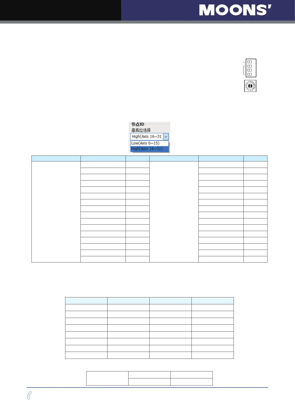
Set drive’s RS-485 Node ID by rotary switch S1
Set drive’s RS-485 baud rate and terminal resistor by piano switch S2
S1 is used to set drive’s RS-485 address, and the range is 0~F (0~15 in decimal). If you want to
set the RS-485 Node ID range to 10~1F(16~31 in decimal), you need to configure it in Step-Servo
Quick tuner software.
高低位选择 S1旋转开关位置 SCL地址 高低位选择 S1旋转开关位置 SCL地址
Lower(Axis 0~15)
0 0
Upper(Axis 16~31)
0 @
1 1 1 !
2 2 2 "
3 3 3 #
4 4 4 $
5 5 5 %
6 6 6 &
7 7 7 '
8 8 8 (
9 9 9 )
A : A *
B ; B +
C < C ,
D = D -
E > E .
F ? F /
S2 used to set the RS-485 baud rate, SW1, SW2 and SW3 are used to set the baud rate. SW4 is
used to set the terminal resistor.
RS-485/422 communication baud rate
SW1 SW2 SW3 Baud rate
(
bps
)
OFF OFF OFF 9600
OFF OFF ON 19200
OFF ON OFF 38400
OFF ON ON 57600
ON OFF OFF 115200
ON OFF ON /
ON ON OFF /
ON ON ON /
Terminal resistor
SW4
OFF Disconnected
ON Connected
S2
S1
RS-485波特率
终端匹配电阻
SW3
SW4
SW2
SW1
RS-485地址

 Loading...


