Debug LEDs
MOTOROLA Technical Summary 2-7
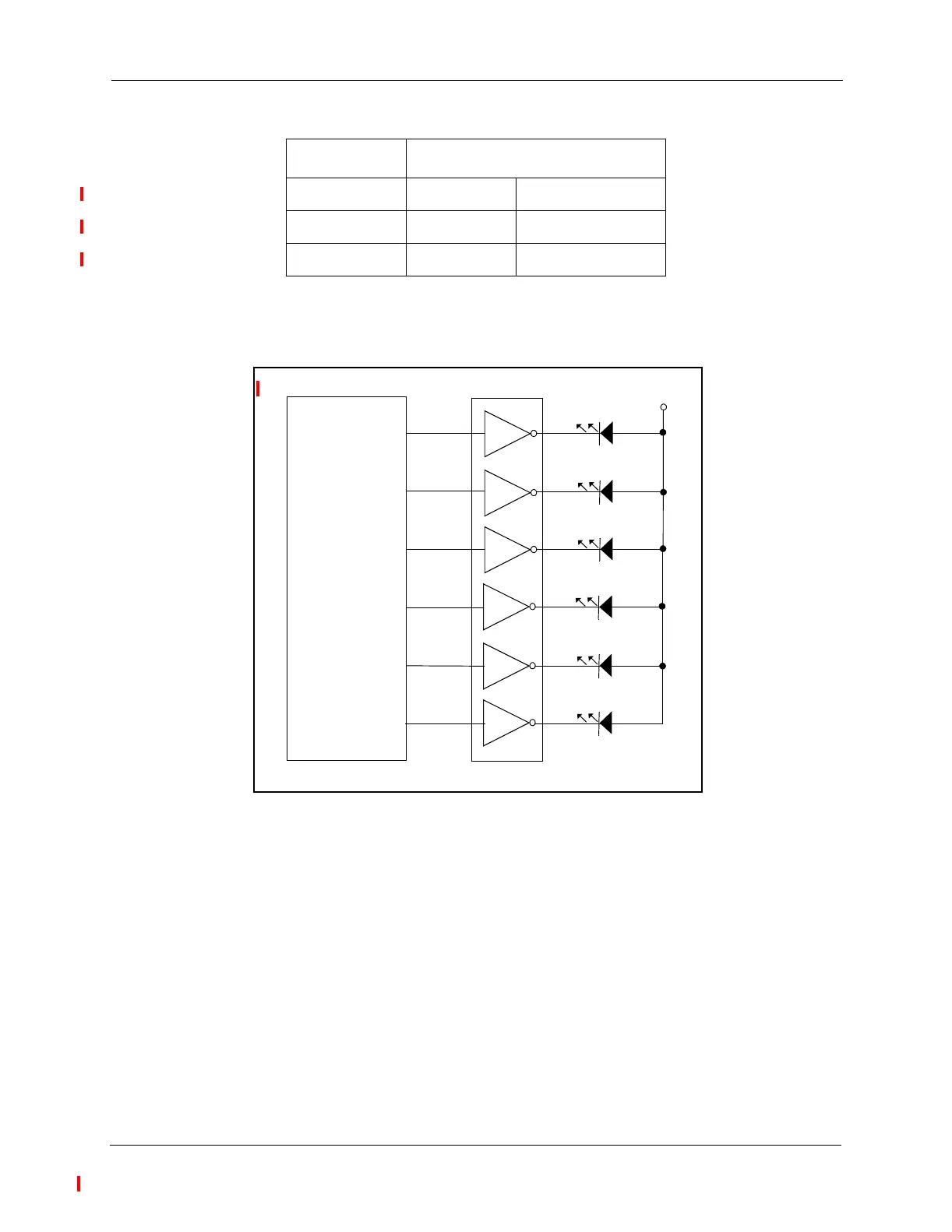
Setting PC0, PC1, PC2, PC3, PC4 or PC5 to a Logic One value will turn on the associated
LED.
Figure 2-3. Schematic Diagram of the Debug LED Interface
LED4 RED GPIO Port C Bit 3
LED5 YELLOW GPIO Port C Bit 4
LED6 GREEN GPIO Port C Bit 5
Table 2-4. LED Control
Controlled by
56F8323 INVERTING BUFFER
PC0
PC1
PC2
GREEN LED
YELLOW LED
RED LED
+3.3V
GREEN LED
YELLOW LED
RED LED
PC3
PC4
PC5
Frees
cale Semiconductor,
I
Freescale Semiconductor, Inc.
For More Information On This Product,
Go to: www.freescale.com
nc...
 Loading...


