Do you have a question about the Motorola XTS1500 and is the answer not in the manual?
Steps to power on the radio, its self-test LED behavior, and waiting for system registration.
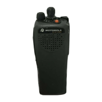
Instructions for changing radio zones using Side Button 1 and selecting talkgroups via the selector knob.
Procedure for transmitting, including listening for talkgroup availability and using the push-to-talk button.
Explanation of chirping sound for low battery and 'bonk' sound for busy channels/systems.
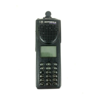
Details on A/B/C Switch, Orange Button (Emergency Use), Purple Button (Display), Side Button 1 (Zone Change), and Side Button 2.
Information on the On/Off/Volume knob, Talkgroup Selector Knob, and Push-to-Talk button.
Description of the Bi-Color LED status indicators and labels for ZONE, TALKGROUP, and Radio ID.
Location and use of the accessory connector on the right side of the radio.
Steps to power on the radio, its self-test LED behavior, and waiting for system registration.
Instructions for changing radio zones using Side Button 1 and selecting talkgroups via the selector knob.
Procedure for transmitting, including listening for talkgroup availability and using the push-to-talk button.
Explanation of chirping sound for low battery and 'bonk' sound for busy channels/systems.
Details on A/B/C Switch, Orange Button (Emergency Use), Purple Button (Display), Side Button 1 (Zone Change), and Side Button 2.
Information on the On/Off/Volume knob, Talkgroup Selector Knob, and Push-to-Talk button.
Description of the Bi-Color LED status indicators and labels for ZONE, TALKGROUP, and Radio ID.
Location and use of the accessory connector on the right side of the radio.
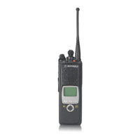
The Motorola XTS1500 Portable Radio is a robust communication device designed for emergency management and other professional uses, as detailed in the provided WARN 01 thru WARN 12 documentation. This radio facilitates reliable two-way communication within various zones and talkgroups, making it an essential tool for coordinated operations.
At its core, the Motorola XTS1500 serves as a portable radio for transmitting and receiving voice messages. It operates within a defined system, allowing users to select specific zones and talkgroups to communicate with relevant personnel. The radio's primary function is to enable clear and efficient communication in critical situations, ensuring that messages are conveyed accurately and promptly. It supports a range of operational modes, from general communication within a talkgroup to specific command and tactical operations, as indicated by the various talkgroup designations like "SCEM OP1," "SEM TAC," and "SL ROAM." The device is designed to be user-friendly, with intuitive controls for power, volume, zone selection, and talkgroup selection, making it accessible even in high-stress environments. Its ability to connect to a radio system and transmit messages after receiving a "talk permit" tone ensures organized and non-overlapping communication.
The Motorola XTS1500 offers several features that enhance its usability and operational effectiveness:
While the document does not explicitly detail a comprehensive maintenance schedule, it does provide crucial information regarding battery management, which is a key aspect of device maintenance:
In summary, the Motorola XTS1500 Portable Radio is a purpose-built communication device designed for reliability and ease of use in demanding environments. Its array of features, from intuitive controls and clear status indicators to essential audio feedback and battery management cues, collectively ensure effective and uninterrupted communication for emergency management and other critical operations.
| IP Rating | IP54 |
|---|---|
| GPS | No |
| Power Output | 1-5W |
| Battery Life | Up to 10 hours |
| Display | Alphanumeric LCD |
| Encryption | AES, DES |
| Battery Type | NiMH |
| Trunking | Motorola SmartNet/SmartZone |
| Signaling | MDC1200, DTMF, Quick Call II |
| Operating Temperature | -30°C to +60°C (-22°F to +140°F) |
| Dimensions | 5.3" H x 2.3" W x 1.5" D (with standard battery) |