Outdoor Unit Disassembly 41
Procedure Illustration
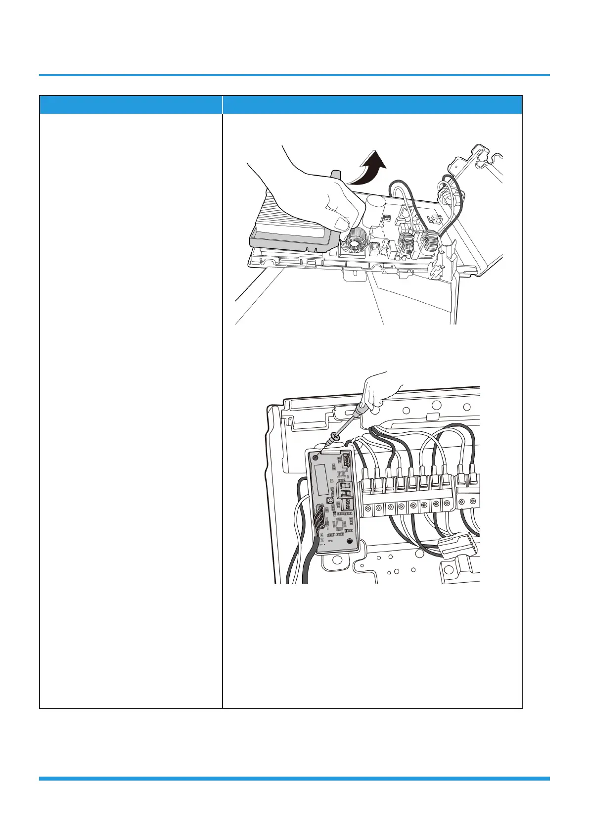
6) Disconnect the connectors from
the electronic control board (see
CJ_ODU_Multi_PCB_006-6).
7) Remove 2 screws and then remove
the electronic control board.(see
CJ_ODU_Multi_PCB_006-6).
8) Pull out the connector, remove one
screw and then remove the key
board subassembly on terminal
board. (see CJ_Multi_PCB_006-7).
CJ_ODU_Multi_PCB_006-6
CJ_Multi-PCB_006-7
Note: This section is for reference only. Actual unit appearance may vary.
 Loading...