2-25
Hardware Setup
+
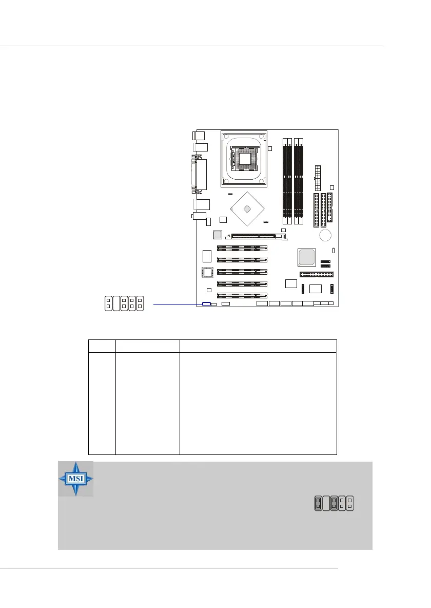
Front Panel Audio Connector: JAUD1
The JAUD1 front panel audio connector allows you to connect to the
front panel audio and is compliant with Intel
®
Front Panel I/O Connectivity
Design Guide.
PIN SIGNAL DESCRIPTION
1 AUD_MIC Front panel microphone input signal
2 AUD_GND Ground used by analog audio circuits
3 AUD_MIC_BIAS Microphone power
4 AUD_VCC Filtered +5V used by analog audio circuits
5 AUD_FPOUT_R Right channel audio signal to front panel
6 AUD_RET_R Right channel audio signal return from front panel
7 HP_ON Reserved for future use to control headphone amplifier
8 KEY No pin
9 AUD_FPOUT_L Left channel audio signal to front panel
10 AUD_RET_L Left channel audio signal return from front panel
JAUD1 Pin Definition
MSI Reminds You...
If you don’t want to connect to the front audio
header, pins 5 & 6, 9 & 10 have to be jumpered in
order to have signal output directed to the rear
audio ports. Otherwise, the Line-Out connector on
the back panel will not function.
JAUD1
1
2
9
10
5
6
10
9
 Loading...