EasyManuals Logo
Home>MSI>Motherboard>A68HM-E33 V2 Series

MSI A68HM-E33 V2 Series User Manual

MSI A68HM-E33 V2 Series
170 pages
To Next Page IconTo Next Page
To Previous Page IconTo Previous Page
Page #18 background imageLoading...
Page #18 background image
English
18
Internal Connectors
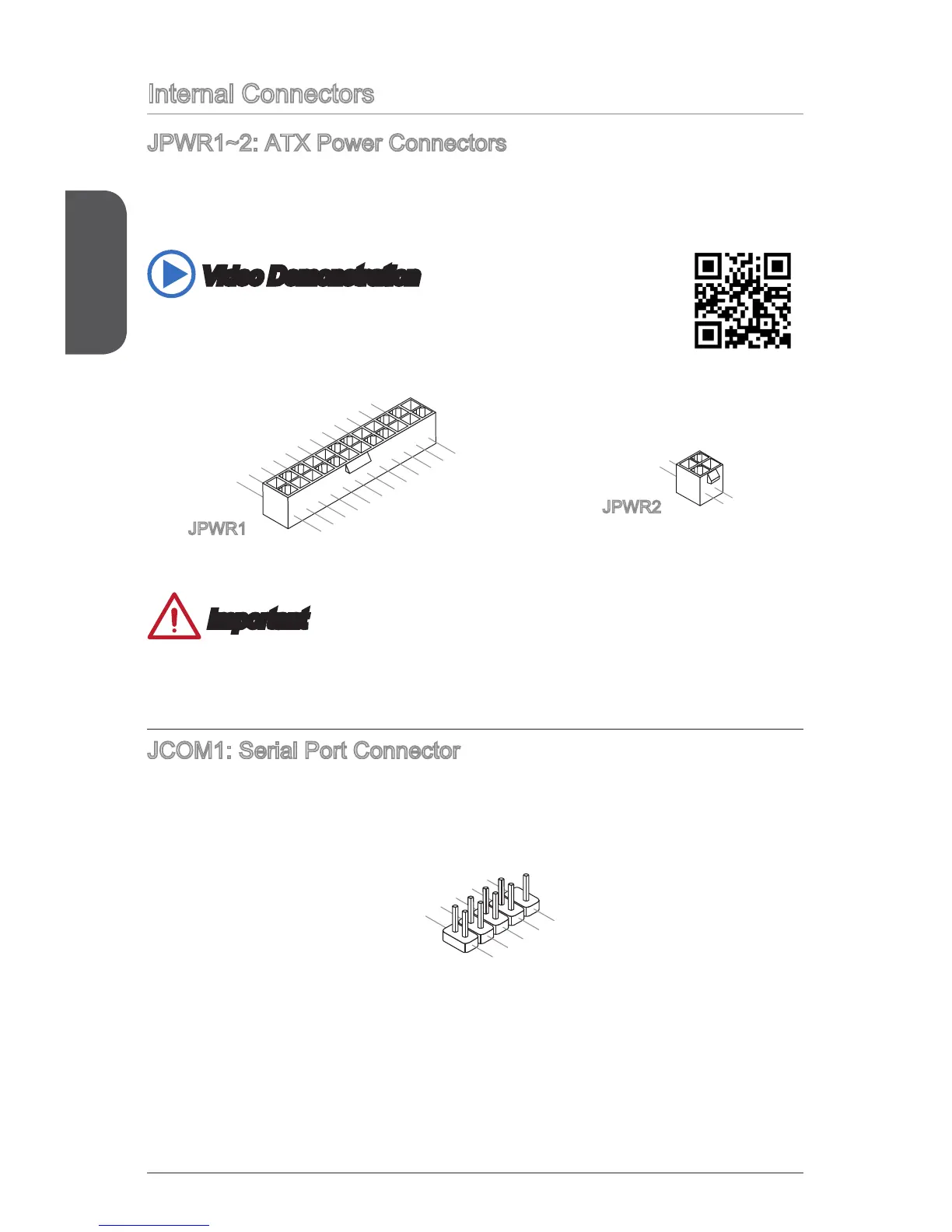
JPWR1~2: ATX Power Connectors
These connectors allow you to connect an ATX power supply. To connect the ATX
󰘰
cable into the connector. If done correctly, the clip on the power cable should be
hooked on the motherboard’s power connector.
Video Demonstration
Watch the video to learn how to install power supply connectors.
http://youtu.be/gkDYyR_83I4
13.+3.3
V
1.+3.3
V
14.-12V
2.+3.3V
15.Ground
3.Ground
16.PS-ON#
4.+5V
17.Ground
5.Ground
18.Ground
6.+5V
19.Ground
7.Ground
22.+5V
10.+12V
20.Res
8.PWR OK
23.+5V
11.+12V
21.+5V
9.5VSB
24.Ground
12.+3.3V
JPWR1
4.+12V
2
.Ground
3.+12V
1
.Ground
JPWR2
Important
Make sure that all the power cables are securely connected to a proper ATX power
supply to ensure stable operation of the motherboard.
JCOM1: Serial Port Connector
This connector is a 16550A high speed communication port that sends/receives 16
bytes FIFOs. You can attach a serial device.
1
.
D
C
D
3
.
S
O
U
T
1
0
.
N
o
P
i
n
5
.
G
r
o
u
n
d
7
.
RT
S
9
.
R
I
8
.
C
T
S
6
.
D
S
R
4
.
D
T
R
2
.
S
I
N

Questions and Answers:

Question and Answer IconNeed help?

Do you have a question about the MSI A68HM-E33 V2 Series and is the answer not in the manual?

MSI A68HM-E33 V2 Series Specifications

General IconGeneral
BrandMSI
ModelA68HM-E33 V2 Series
CategoryMotherboard
LanguageEnglish

Related product manuals