1-13
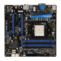
MS-7697
Chapter 1
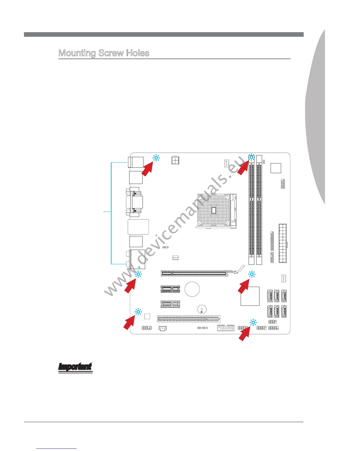
Mountng Screw Holes
When nstallng the manboard, rst nstall the necessary mountng stands requred for
an manboard on the mountng plate n your computer case. If there s an I/O back plate
that came wth the computer case, please replace t wth the I/O backplate that came
wth the manboard package. The I/O backplate should snap easly nto the computer
case wthout the need for any screws. Algn the mountng plate’s mountng stands wth
the screw holes on the manboard and secure the manboard wth the screws provded
wth your computer case. The locatons of the screw holes on the manboard are shown
below. For more nformaton, please refer to the manual that came wth the computer
case.
Important
Install the manboard on a at surface free from unnecessary debrs.
To prevent damage to the manboard, any contact between the manboard crcutry
and the computer case, except for the mountng stands, s prohbted.
Please make sure there are no loose metal components on the manboard or wthn
the computer case that may cause a short crcut of the manboard.
•
•
•
The I/O ports should be facng toward
the rear of the computer case. They
should lne up wth the holes on the
I/O backplate.
 Loading...