En-10
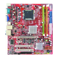
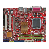
MS-7528 Mainboard
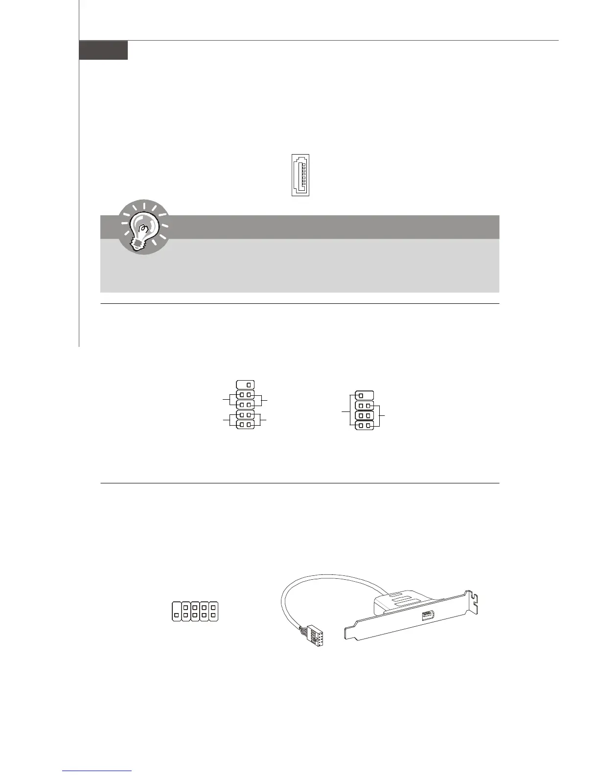
Front Panel Connectors
These connectors are for electrical connection to the front panel switches and LEDs.
The JFP1 is compliant with Intel
®
Front Panel I/O Connectivity Design Guide.
IEEE1394 Connector (Green)
This connector allows you to connect the IEEE1394 device via an optional IEEE1394
bracket.
Serial ATA Connector
This connector is a high-speed Serial ATA interface port. Each connector can connect to
one Serial ATA device.
Important
Please do not fold the Serial ATA cable into 90-degree angle. Otherwise, data
loss may occur during transmission.
IEEE1394 Bracket
(Optional)
JFP1
1
2
910
HDD
LED
Reset
Switch
Power
LED
Power
Switch
JFP2
78
Power LED
Speaker
12
1
2
9
10
TPA-
Ground
TPB-
Ground
TPA+
Ground
TPB+
Cable power
Key (no pin)
PDF 檔案使用 "pdfFactory" 試用版本建立 www.ahasoft.com.tw/FinePrint
 Loading...