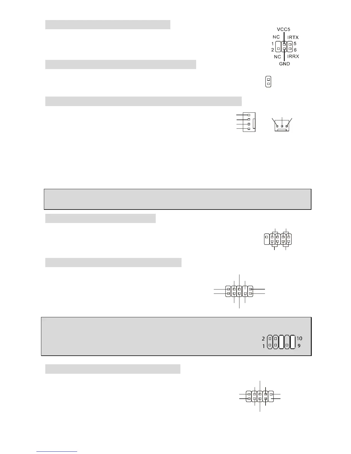
IrDA Infrared Module Header: JIR1
The connector allows you to connect to IrDA Infrared module and is compliant
with Intel Front Panel I/O Connectivity Design Guide. You must configure the
setting through the BIOS setup to use the IR function.
Chassis Intrusion Switch Connector: JC1
This connector is connected to a 2-pin chassis switch. JC1 is compliant with
Intel
®
Front Panel I/O Connectivity Design Guide.
Fan Power Connectors: CPU_FAN/SYS_FAN(optional)
The 4-pin CPU_FAN (processor fan), 3-pin SYS_FAN
(system fan) support system cooling fan with +12V.
CPUFAN can support three- or four-pin head connector.
When connecting the wire to the connectors, always take
note that the red wire is the positive and should be
connected to the +12V, the black wire is Ground and should be connected to GND. If the
mainboard has a System Hardware Monitor chipset on-board, you must use a specially designed
fan with speed sensor to take advantage of the CPU fan control.
MSI Reminds You...
Always consult the vendors for the proper CPU cooling fan.
Front Panel Connectors: JFP1
The mainboard provides two front panel connectors for electrical connection
to the front panel switches and LEDs. JFP1 is compliant with Intel
®
Front
Panel I/O Connectivity Design Guide.
Front Panel Audio Connector: JAUD1
The front panel audio connector allows you to
connect to the front panel audio and is
compliant with Intel
®
Front Panel I/O
Connectivity Design Guide.
MSI Reminds You...
If you do not want to connect to the front audio header, pins 5 & 6, 9 & 10 have
to be jumpered in order to have signal output directed to the rear audio ports.
Otherwise, the Line-Out connector on the back panel will not function.
Front USB Connector: JUSB1/JUSB2
The mainboard provides two standard USB 2.0 pin headers
JUSB1&JUSB2. USB2.0 technology increases data transfer
rate up to a maximum throughput of 480Mbps, which is 40
times faster than USB 1.1, and is ideal for connecting
high-speed USB interface peripherals such as USB HDD,
(2)AUD_GND
AUD_VCC
 Loading...