2-16
Hardware Setup
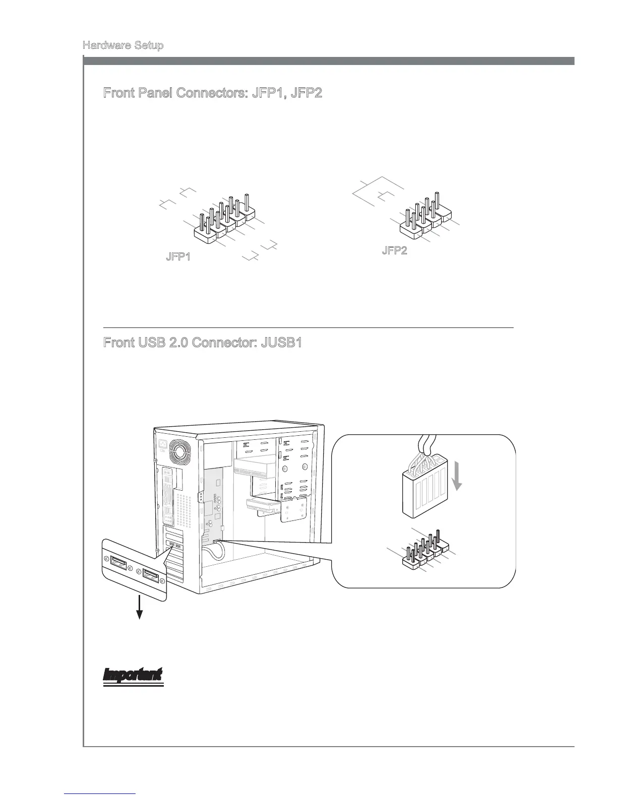
Front Panel Connectors: JFP1, JFP2
These connectors are for electrcal connecton to the front panel swtches and LEDs.
The JFP1 s complant wth Intel
®
Front Panel I/O Connectvty Desgn Gude.
1
.Ground
3.Suspend
LE
D
5.Power
LE
D
7.No Pi
n
8.
+
6.
-
4.
+
2.
-
Buzzer
S
peaker
1.+
3.
-
10.No
Pi
n
5.
-
Reset
S
witch
HDD
LE
D
P
ower
S
witch
P
ower
LE
D
7.
+
9.Reserve
d
8.
-
6.
+
4.
-
2.
+
JFP1
JFP2
Front USB 2.0 Connector: JUSB1
Ths connector, complant wth Intel
®
I/O Connectvty Desgn Gude, s deal for con-
nectng hgh-speed USB nterface perpherals such as USB HDD, dgtal cameras, MP3
players, prnters, modems and the lke.
1.VC
C
3.USB0
-
10.NC
5.USB0
+
7
.Ground
9.No
Pin
8
.Ground
6.USB1
+
4.USB1
-
2.VC
C
* The MB layout n ths gure s for reference only.
USB 2.0 Bracket (optonal)
Important
Note that the pns of VCC and GND must be connected correctly to avod possble
damage.
 Loading...