En-13
Englsh
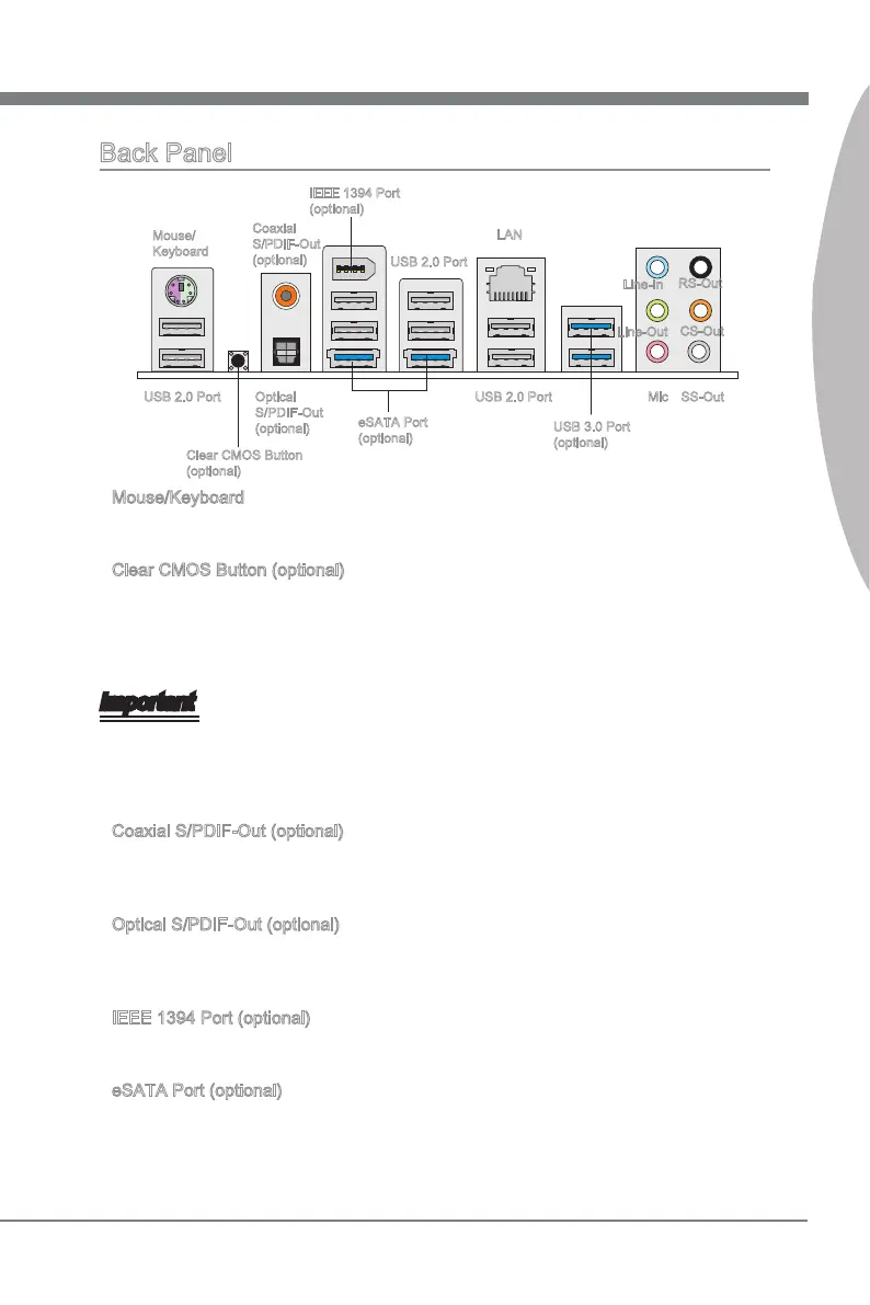
Back Panel
Mouse/Keyboard
The standard PS/2
®
mouse/keyboard DIN connector s for a PS/2
®
mouse/keyboard.
Clear CMOS Button (optonal)
There s a CMOS RAM on board that has a power supply from external battery to keep
the system conguraton data. Wth the CMOS RAM, the system can automatcally
boot OS every tme t s turned on. If you want to clear the system conguraton, use
the button to clear data. Press the button to clear the data.
Important
Make sure that you power o the system before clearng CMOS data.
After pressng ths button to clear CMOS data n power o (G3) state, the system wll
boot automatcally.
Coaxal S/PDIF-Out (optonal)
Ths SPDIF (Sony & Phlps Dgtal Interconnect Format) connector s provded for dgtal
audo transmsson to external speakers through a coaxal cable.
Optcal S/PDIF-Out (optonal)
Ths SPDIF (Sony & Phlps Dgtal Interconnect Format) connector s provded for dgtal
audo transmsson to external speakers through an optcal ber cable.
IEEE 1394 Port (optonal)
The IEEE 1394 port on the back panel provdes connecton to IEEE 1394 devces.
eSATA Port (optonal)
The eSATA (External SATA) port s for attachng the eSATA hard drve.
▶
▶
•
•
▶
▶
▶
▶
Mouse/
Keyboard
LAN
Lne-In
Lne-Out
Mc
IEEE 1394 Port
(optonal)
USB 3.0 Port
(optonal)
RS-Out
CS-Out
SS-OutUSB 2.0 Port
Clear CMOS Button
(optonal)
Optcal
S/PDIF-Out
(optonal)
Coaxal
S/PDIF-Out
(optonal)
USB 2.0 Port
eSATA Port
(optonal)
USB 2.0 Port