1
Contents
Contents
3
4
10
LAN Port LED Status Table ......................................................................................11
Audio Ports Configuration ........................................................................................11
12
CPU Socket ...............................................................................................................13
DIMM Slots................................................................................................................14
DIMM Slots................................................................................................................14
PCI_E1~4: PCIe Expansion Slots ..............................................................................15
JFP1, JFP2: Front Panel Connectors .......................................................................16
SATA1~6: SATA 6Gb/s Connectors ...........................................................................17
JAUD1: Front Audio Connector ................................................................................17
M2_1~4: M.2 Slot (Key M) .........................................................................................18
ATX_PWR1, CPU_PWR1~2: Power Connectors .......................................................19
JUSB1~2: USB 2.0 Connectors .................................................................................20
JUSB3~4: USB 3.2 Gen 1 5Gbps Connector .............................................................20
JUSB5: USB 3.2 Gen 2 Type-C Connector ................................................................21
JTBT1: Thunderbolt Add-on Card Connector ..........................................................21
CPU_FAN1, PUMP_FAN1, SYS_FAN1~6: Fan Connectors ......................................22
JTPM1: TPM Module Connector ...............................................................................22
JCI1: Chassis Intrusion Connector ...........................................................................23
JDASH1: Tuning controller Connector .....................................................................23
JBAT1: Clear CMOS (Reset BIOS) Jumper ...............................................................24
JRAINBOW1~2: Addressable RGB LED connectors ................................................24
JRGB1: RGB LED connector .....................................................................................25
EZ Debug LED ...........................................................................................................25
26
Installing Windows® 10 .............................................................................................26
Installing Drivers ......................................................................................................26
MSI Center ................................................................................................................26
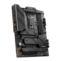
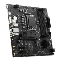
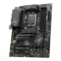
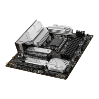
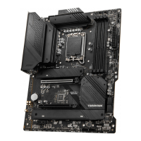
Thank you for purchasing the MSI®
motherboard. This User Guide gives
information about board layout, component overview, BIOS
setup and software installation.