C and D series mowers
54
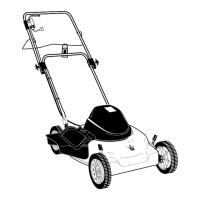
11. When assembled correctly, the sweep of the single
cam slot should match the sweep of the lobes on the
rotor, guiding the pawl to seat in the hook at the trail-
ing edge of each lobe in the rotor. See Figure 4.69.
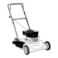
12. The A-side drag plate contains four cam slots.
See Figure 4.70.
• The A-side drag plate has a notch in it that will
catch on the spring arm on the bearing retainer.
• When the A-side drag plate lags relative to the
axle, the cam slot pulls the pawl control pin
inward, engaging drive to the A-side rotor and
the long axle.
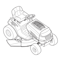
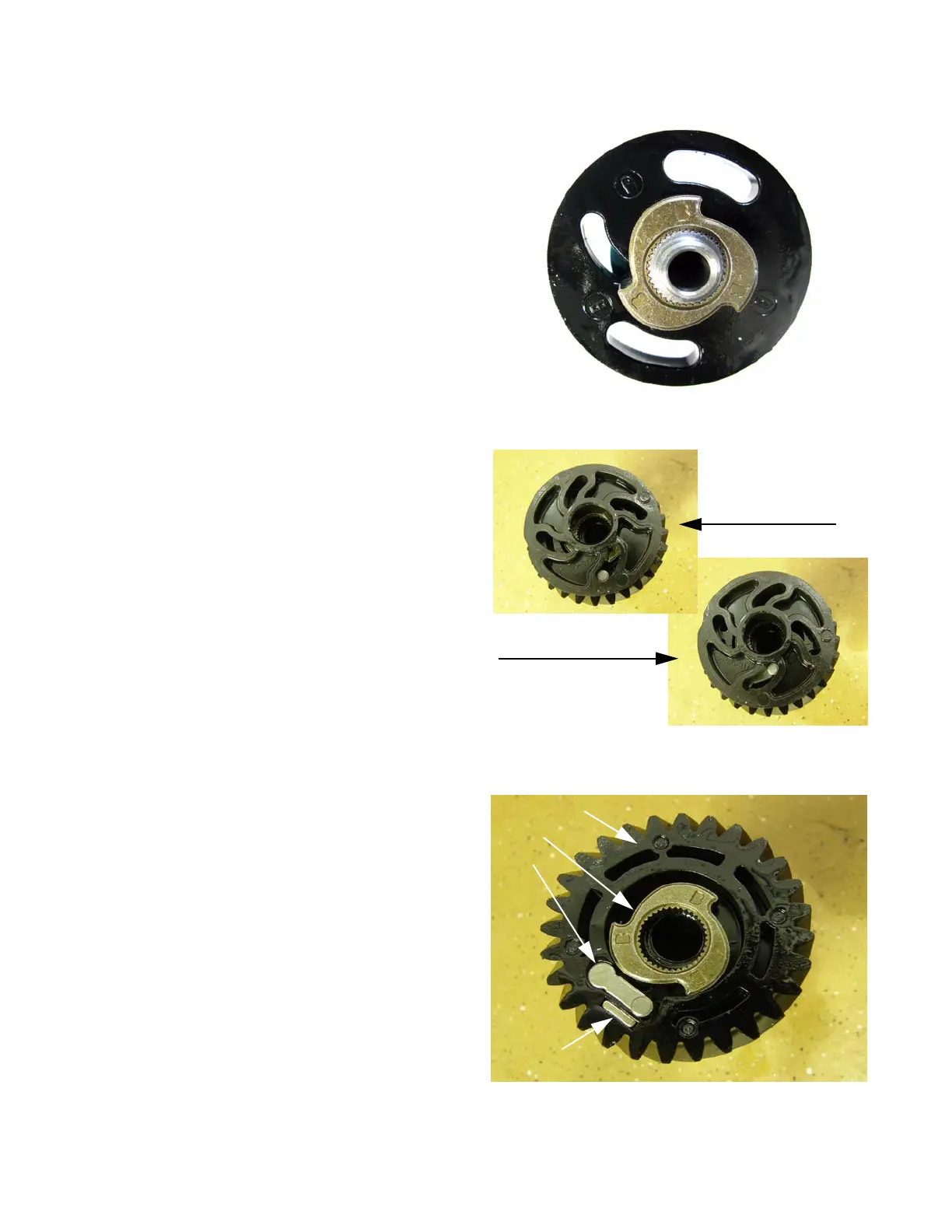
13. The A-side pawl is held outward by a small magnet
that fits in the pinion gear. See Figure 4.71.
NOTE: In this picture, the “B”s are visible on the
rotor beacuse we are looking at the outward
facing side of the rotor. It is correctly posi-
tioned in the A side of the helical gear. Most
production rotors are only marked on the A
side.
Figure 4.69
Figure 4.70
Pawl disengaged
Pawl engaged
Figure 4.71
Helical gear
Rotor
Pawl
Magnet
 Loading...