Building
Instructions
Pleass
read these inl.uctlons
thoroughly
b€fore Startlng
work.
Compare
the
individual comoonents
with
the Pans List and
the
plan;
this
will
avoid
errors
in building,
and will speed
assembly.
It is best
to
keep to the
tollowing sequence
when building
the
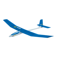
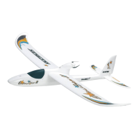
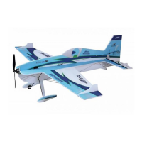
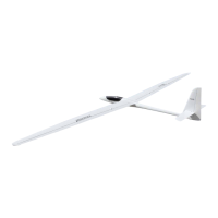
'Alpina':
a Construction
ol tailplane
and
rudder'
a
Fitting of tail
components
to the luselage.
a
Installation of wing
joiner
unit
in the tuselage.
a Fitting
the
plywood parts
nto lhe
tuselage
a Capony
and latch.
a
Finishing the
wings.
a Covering
and
-
if
desjred
-
painting
Installation
of radio, and
linal adjustments.
The following
adhesives should
be used:
Foam
-
wood: white
glue,
s-minute epoxy,
Copydex,
and any other
glues
which
do not atlack
loam. Do
not
use
solvent based
glues;ifin
doubt,
try
the
adhesive
on a
piece
ol scrap
foam
Wood
-
wood:
white
glue,
instantglue
(Cyano'acryiate),
Uhu'hart' 5-minute
epoxy,
and olher
wooo
glues.
GRP
-
wood:
slow-setting
epoxy, s-minute
epoxy.
--eparatory
wolk on the
wlngs
-;e
lirst
task is to bond
the steel blades
22 and
the locating
pins
29 into the
wing
roots. lt is
imporlant to use a
high
quality,
slow-setting
epoxy
here On
no
accounl
use s-minute
glue,
such
as Devcon or
similarl
Slide
the steel
blades
into the
wings and check
thal no
more lhan 90
m m
proiecls
lrom
the root. De'grease
the blades
Now stand
the wing
panels
on
theirtips,
as nearly
vertical as
possible,
and
pourresin
intotheslots
Makesure
theglue
coats
allthe surfacesinside
by stirring
itwith a length of
wire lnsortthe
blades, check
the
proiecting length again,
and fillthe slots
with resin
until the
surfaces
are
flush. Glue
the locating
pins
29 in
place
in the same
way-the
plns
should
proiect
13
m.m. Leave lhe
wings standing
vertical
overnight
for the
resrn Io cure.
Tallolane
and
rudder
To complete
the
tailplane
panels
1 il is
only
necessary
to fit lhe tips 2. Glue
them in
place
as
per plan,
and
sand to shape.
The veneer covering
is
only
1
m.m.
thick
(to
save
weight), so take
care not to sand
through it
Glue
thetopand bottom
blocks
(4
and
5)to the rudder 3.
When
gluing
block 5
in
place,
be sure
lo tit il
far
enough
forwards
to
accommodate
the
slope
ol the
leading edge.
Sand
the blocks tlush
with the leading edge ol
the rudder'
Glue
skip 6
to the leading edge
ol the
rudder. Let all the
glued
ioints
dry
thoroughly,
then sand
the two blocks and
svip 6 to
tinal
shape,
takang care
gain
not tosand
through the
veneer. Sand an angleol
aboul
l5oeither
sideol
-{fie
centre
line
olstrrp
6,lo
allowthe
rudderto
pivot
(see planJ.
Todolhis
mark
the centre
line with a
felt-tip
pen
before
sanding the bevels
Finish
with a razor-
plane,
set
very line, to ensure
sharp corners
Fuselage
The
tailplane and
rudder can
now be attached
tothe luselage.
Thefirstjob
here
is to
fitthe all-flying
tailplane
bellcrank
7 into thelin. Take specialcare
overthis,
as
the
model's handling
in llight depends
on this assembly
operating
freely and
precisely
{Jll.
1).
Drill
the
pivot
tube holes
out to 4 m.m. on
both sides ol
the luselage
where
marked.
Pilot drill
the cutued slots
for the
rear tailplane dowel,
and fil6 out
exactly
to the shape
shown,
using a
half'round tile.
Fit
the bellcrank
7 onto shaft 8,
lollowed
by bushes 9, as
shown on
the
plan.
The tubes
ol the bushes
should
point
outwards
Fitthe assembled
bellcrank,
with bushes,
intothelin,
butdonotglueyet
Fitlhe
tailolane Danels
onto
the two
wire dowels
10,
after
bending
the dowels
genlly
at
the ends
to stop
the tail
panels
slipping otf.
Thetailplane
must be at
right angles
to the lin, and
the tailplan€
roots must alsofit
neatly up tothefin
on both sides.
lf
necessary,
lile out
the holes in the
fin with a
round file Remove
the bellcrank
from
the fuselage.
Using
a small
amount of
5-minute epoxy,
assemble
the bellcrank'
shall and
bushes outside
lhe
fuselage.
lvlake sure
that no
glue gets
onto the bellcrank
There should
bea
gap
ot about0.5
m.m on either side
ol the crank' so
that the
crank
can
pivot
treely.
When
the epoxy has set,
check again
tor lrssdom of
movemenl,
and
free the assembly
if it has
iammed
Solder a
threaded coupler
13 onto steel
rod 12.
To
be
sure of a sound
joint'
sand
the end of the
wire clean, and
bend
it
slightly
until
il is
a
tight fit in the
coupler.
lt is essentialto
make sound
solderjoints
on allpushrod
linkages, as
you
cannot atford
a single
lailure
in flight!
Screw clevis
14 onto
the coupler as
far as it willgo.
Apply a drop of contact
glue
to
prevent
it
coming
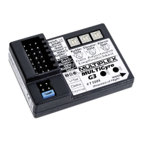
loose. Allthe control
linkages shown
refer to MULTIPLEX
FyC systems;
if
you
are using a
ditfelent
make of radio,
please
follow the
manufaclurer's
recommendations.
Check
tailpost
15 forlit in thefin.
You will have
to round off
the top and bottom
to
fit neatly inside. Check
that the bevelled
leading edge
of the
rudder lines up
with thetailpost accurately.
The lin and ruddershould
have the same
thickness
where
they meet, otheMise
unnecessary
drag willoccur'
Trim back
if neces'
sary.
Fitthe bellcrank
intothe
fuselageagain, sliding
thesteelpushrod
intothe
bowden
cable
guide
tube. Check
that it operates
lreely
The all-tlying
tailplane bellcrank
can now be
permanently glued
into
place.
Support
the
fuselage on the
workbench, with the
fin exactly
vertical. Apply
epoxy
to the outside of
the bushes, slide
the
pushrod
into the bowden cable
guide
tube and
locate the bellcrank
in the
fin. Apply epoxy to
washers 11, and
glue
them into the depressions
on the outside
ofthe
fin. Align carefully,
then fit
the tailplane
panels
and
wire dowels. Leave
a
gap
between
thetailpanels and
the
fin,
otherwise
excess
glue
could bond
them
in
place.
Fit tailpost
15 and tape
it in
place (do
not
glue
yet).
Check
the tailplane
for
correct
alignment
in
plan
viewas
wellas lrom
the front and
rear.
Supportthe
tail
panels
until the epoxy
has cured.
Checkthat
the tailplane controlworks
correctly,
and adjust
if necessary.
lt must
move lreely
to the top and bottom
of the curved
slot without any
jamming
or
tight spots.
Remove
the tail
panels.
Sand
the
projecting
ends of the
tailplane bellcrank
bushes
flush with the
surface
of
the fin, and remove
any excess
glue.
Take
great
care hele, as
you
might damage
the surlace
of the fin.
Slide the bowden
cable
innersleeve
16
onto
the steel
pushrod
hom the cockpit
end.
The Inner sleeve
must
not be
glued
tothe
steel
pushrod,
asthis would
cause binding.
Tailpost 15 can
now be
gtued
into
place.
Before
gluing,
the
hole for the rudder
linkage
has to be drilled.
l\,leasure otf
the
position
of the end of
the
bowden
cable
guide
tube,
and mark
the
position
on
the
outside
of the
fuselage Pilotdrill
the hole
where shown, and
lile out to the correct
shape.
Glue
thetailpost
15 into
place,
using a slow-sening
epoxy. Clamp
the lin to the
tailpost, using
balsa strips
(not
supplied)
to
prevent
damage
and spread
the
damping
force.
lt is
agood
idea
heretotape the strips
in
place
belore attaching
the clamps. Check
the
fin for distortion by
sighting
from above, and adiust
il
necessary by undoing
the clamps and
twisting
. The fin must be exactly
in line
with the
fuselage!
Sand
the rear ofthe
fin llush, then bevelboth
sides
as described beforeforthe
leading edge ol
the rudder.
Cul slots
for lhe
rudder hinges,
using a sharp balsa
knife.
The hlnges are nol
glued
in
place
untll afler coverlng
the
rudde..
The rudder
linkage is made
up next. Cut a
slot lor lhe
rudder horn
18 in the
position
shownonthe
plan.
Gluethe
horn in
placeusing
s-minuteepoxy.
Apply
tape
round the edges ot
theslotto
prevent
excess
glue
adhering
to the rudder.
Remove the
tape when the
glue
has set.
Bend steel
pushrod
12 as
per plan
and slip
it into the bowden
cable
guide
tube
through
the hole at the
rear of the
fuselage. Bend
the tail end ol
the
pushrod
down slightly,
sothatit
is held inthe
horn under
gentle
tension
Noothermeans
of
retaining the
pushrod
is
needed.
Thetailend is nowcomplete.
The next stage covers
the installation
ol the wing
ioinsr
unit
and fuselage
reinforcements.
Drill 3
m.m. holes
where marked on
the wing
root lairings
to take the wing
locating
pins.
Pilot drillthe
holes forthe
wing
ioiner
unit,
and lile out
to
shape.
Transfer the
position
ol
the aileron and
airbrake
pushrod holes from the
wing
roots to the
fuselage, and drilllhem
8 m.m.
lt is
best
to
pilot
drillthese
holes
with
a smaller
drill and
file them out to
full
size.
This
will avoid damaging
the
tuselage.
Check
fuselage r€inforcement
19
for fit in the fuselage
and
glue
in
place
with
slow-setting
epoxy.
Take
great
care
not to
push
the tuselage
sldes apart
here, as
thls would
result In lhe wings
havlng unwanted
sweep.
The two
vertical
faces
of
the wing
root fairings must be
absolulely
parallel
l{ a
vernier
caliper
is available, check
that this
is
so.
Moasure at
the centre ol
the leading
edge radius and
at the trailing
edge.
The
wing
joiner
is assembled
next; it consists
ol
parts
20 to 28
(see
Jll
2).
Screw
together the sliding clamp
(parts
23 to 28),
not forgetting
to
press
the
hollow rivet into the
rear face ol clamp
24. The unit
will not clamp
up
properly
withoul
it.
11
 Loading...