© Munters AB, 2014 5
2 Overview
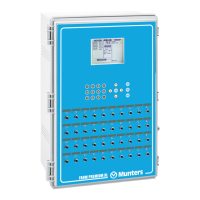
The Munters MUX enables in line communication between controllers and a PC.
• The COMMUNICATION BOX has an AC voltage input on the left side of the box, and
3-communication terminals.
• The left side terminal (RS-232) is connected to the controllers in the houses, the second one
from the left is connected to the modem and the other one is connected to the P.C. as shown in
the wiring diagram.
• The cable which comes from the controllers and connects to the RS-232 terminal should be a 3-
wire shielded cable.
The MODEM input is the priority channel, while the PC is not a priority channel. This means, that in
normal conditions the communication is performed between PC and Controllers. If the demand for
communication comes in from the modem, the PC channel is blocked until the communication with the
MODEM is complete.
NOTE If the communication is not working, try switching the RX and TX pins of the PC terminal.
NOTE Munters recommends the
US Robotics
Modem
.
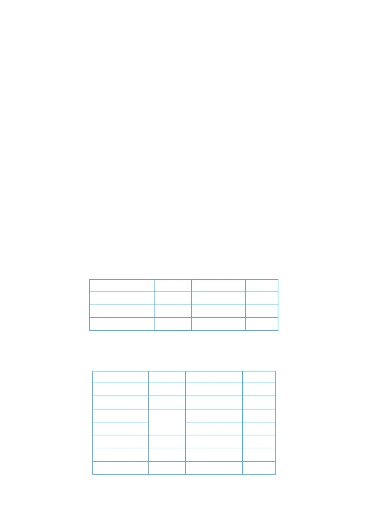
2.1 PC Terminal Connection
Connect the 2-wire cable and shield to the PC (DB-9 connector):
PC Terminal Wire color DB-9 Connector Function
TX Red 2
RX Black 3 Input
COM Shield 5 Output
2.2 Modem Terminal Connection
Connect the 4-wire cable and shield to the Line Modem (DB-25 connector).
Modem Terminal Wire color DB-25 Connector Function
TX Red 2 Output
RX Black 3 Input
-
Short
4
- 5
COM Shield 7
DCD Green 8 Input
DTR White
20
Output
 Loading...